作って意地でも理解する フォントがレンダリングされるまで
いきなりですが、2つ質問です。今まさにあなたが読んでいる文字がどうやってレンダリングされているか説明できますか?私はできませんでした。それではあるモノの仕組みを理解するために最も効率の良い方法は何でしょうか?そう、自作することです!それではフォントのパーサーとレンダラーをゼロから作っていきましょう!
目的
小さなTrueTypeレンダラーを自作し、フォントがレンダリングされるまで流れを理解することが目的です。具体的には、Unicodeのフォントを読み込んで、任意の文字列をレンダリングしpngファイルとして書き出すまでを目標とします。実装はほぼプレーンなC++で、ベクトル演算用にglm、png書き出し用にstb_image_writeを使います。コード全体は以下から確認できます。
TrueTypeとは
TrueTypeとはAppleが1990年に開発したフォントのフォーマットです。その後Microsoftに無償で技術提供され、現在に至るまで標準的なフォントフォーマットの一つとして使われています。TrueTypeの仕様書はAppleの公式サイトから見ることができます。
超ざっくりTrueTypeの仕組み
TrueTypeはグリフにベクター画像を用いることにより、スケーラブルなレンダリングを実現するフォントフォーマットです。つまり、最小構成要素は点で、点を結んで線を作り、線をつなげて輪郭を作り、輪郭を塗りつぶせばグリフをレンダリングできるということです。
TrueTypeにおいて線は直線と曲線の二種類に分類され、曲線は二次ベジエ曲線を用いて表します。そして線をつなぐと輪郭(Contour)になります。グリフの輪郭と言われてもイメージがつきにくいかもしれませんが、たとえば以下の"B"は外側の輪郭が1つ、内側に2つ、合計3つの輪郭で構成されています。
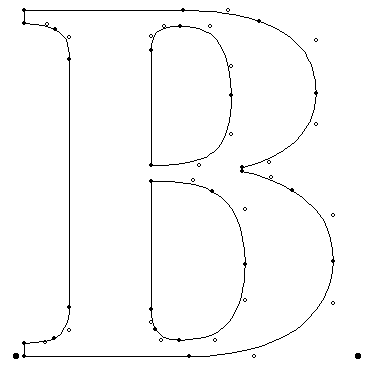
Digitizing Letterform Designs - TrueType Reference Manual - Apple Developerより引用
またグリフによっては、複数のグリフを組み合わせて表現できることもあります。これをコンパウンドグリフと呼びます。例えば、"Ü"は"U"を使ったコンパウンドグリフです。このようにして一つのグリフに必要な輪郭を全て得ることができたら、塗りつぶして完成です。
そしてTrueTypeのデータはテーブルで表されます。テーブルと言ってもバイト列に直接データが詰まっているのであくまで1次元的で、例えばcmapテーブルにアクセスするためにはファイルの先頭からXXXXバイト移動してアクセスするようなイメージです。

この図はあくまでイメージでテーブルの並びやバイト数は適当です
TrueTypeの"輪郭"が少し見えてきたでしょうか?するといくつかの疑問が頭に浮かんでくると思います。グリフのデータにはどうやってアクセスするのか?曲線はどうやってレンダリングするのか?塗りつぶしの方法は?などなど…ここではその感覚を実装に入る前に得られれば十分です。それでは実際にTrueTypeファイルのパースに入っていきましょう!
TrueTypeパーサー グリフデータの取得準備
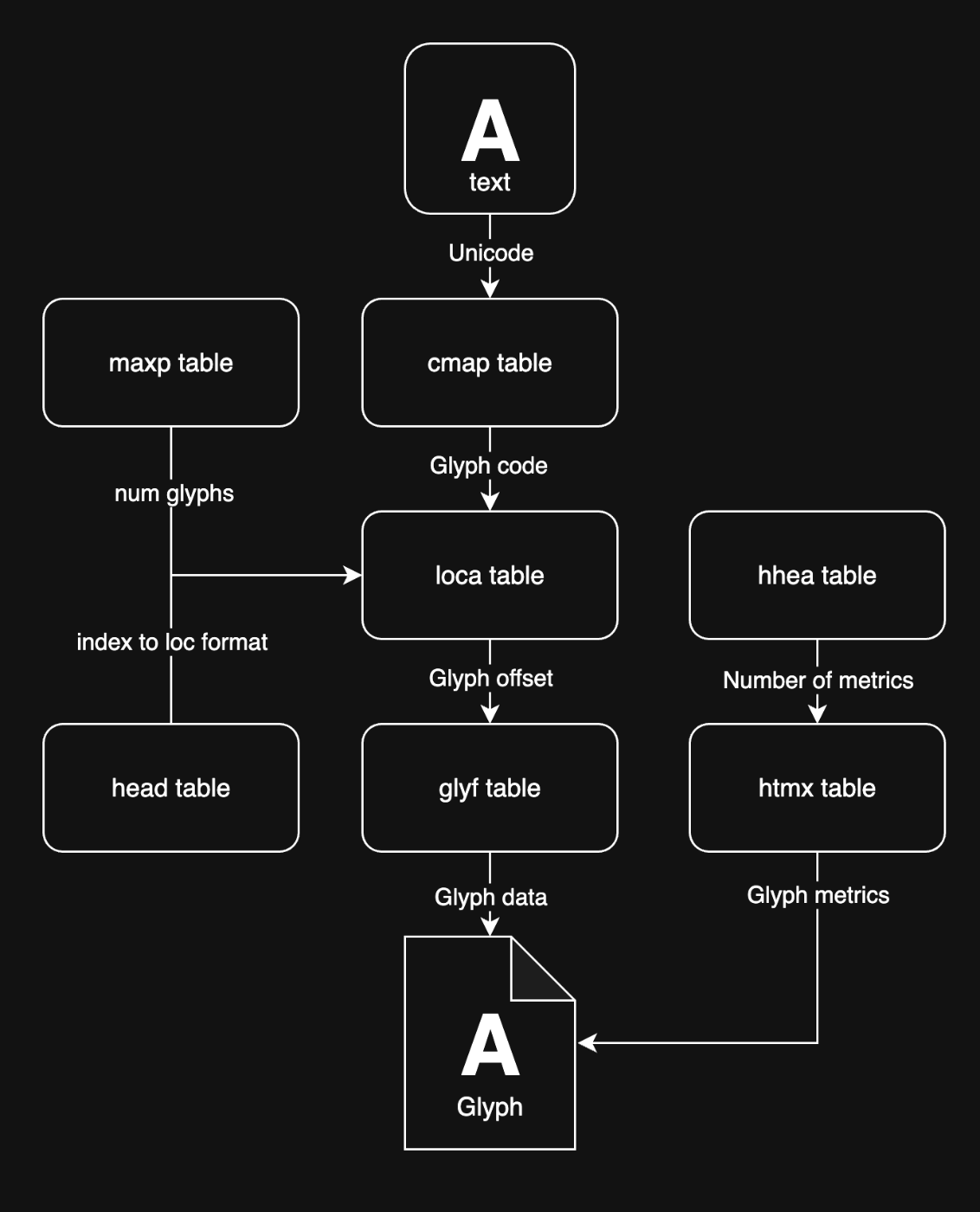
パーサー側の主なゴールはUnicodeからグリフデータを得ることです。ただし一筋縄ではいかず、たくさんのテーブルを見て回ってグリフのための情報を集めてくる必要があります。以下の図はグリフデータを得るまでにアクセスするテーブルのフローです。
ttfファイル読み込み
まずはFontParserクラスを作って.ttfファイルを開き、データにアクセスできるようにします。基本的には特定のバイトオフセットにジャンプして何バイトずつか読み込む、の繰り返しなので、以下のようにナビゲーション用のメソッドを用意します。ここでの実装上の注意点としては、TrueTypeのデータはビッグエンディアンであることです。
ちなみに、TrueTypeにはuint, intなどの一般的な型以外に以下のような特別なデータ型が存在します。特にF2Dot14は精度が必要なグリフの変形に用いられる大事な型なので、合わせてメソッドを作ってしまいましょう。
| 型 | 説明 |
|---|---|
| shortFrac | 16-bit 符号付き小数 |
| Fixed | 16.16-bit 符号付き固定小数点数 |
| FWord | 16-bit 符号付き整数 (単位: FUnit) |
| uFWord | 16-bit 符号なし整数 (単位: FUnit) |
| F2Dot14 | 16-bit 符号付き固定小数点数 上位2ビットが整数部、下位14ビットが小数部 |
| longDateTime | 64-bit 1904年1月1日12:00からの秒数 |
※FUnit: フォント内部で用いられる大きさの単位
Font Tables - TrueType Reference Manual - Apple Developer
データ読み込み用へルパメソッドのコード
FontParser::FontParser(const std::string& path) {
  ifs.open(path, std::ios::binary);
  if (!ifs) std::cerr << "failed to open file\n";
}

void FontParser::skipBytes(const unsigned bytes) {
  ifs.seekg(bytes, std::ios::cur);
}

void FontParser::jumpTo(const unsigned byteOffset) {
  ifs.seekg(byteOffset, std::ios::beg);
}

template <typename T>
T FontParser::readBeOrThrow() {
  uint32_t acc = 0;
  for (std::size_t i = 0; i < sizeof(T); ++i) {
    const int c = ifs.get();
    if (c == EOF) throw std::runtime_error("unexpected EOF");
    acc = (acc << 8) | static_cast<unsigned char>(c);
  }

  if constexpr (std::is_signed_v<T>) {
    const auto bits = static_cast<unsigned>(sizeof(T) * 8);
    const uint32_t sign_mask = (static_cast<uint32_t>(1) << (bits - 1));
    if (acc & sign_mask) {
      const uint64_t two_pow = static_cast<uint64_t>(1) << bits;
      const int64_t signed_val =
          static_cast<int64_t>(acc) - static_cast<int64_t>(two_pow);
      return static_cast<T>(signed_val);
    }
    return static_cast<T>(acc);
  } else {
    return static_cast<T>(acc);
  }
}

uint8_t FontParser::readUint8() { return readBeOrThrow<uint8_t>(); }
uint16_t FontParser::readUint16() { return readBeOrThrow<uint16_t>(); }
uint32_t FontParser::readUint32() { return readBeOrThrow<uint32_t>(); }
int8_t FontParser::readInt8() { return readBeOrThrow<int8_t>(); }
int16_t FontParser::readInt16() { return readBeOrThrow<int16_t>(); }
int32_t FontParser::readInt32() { return readBeOrThrow<int32_t>(); }
float FontParser::readF2Dot14() {
  const auto raw = readBeOrThrow<int16_t>();
  return static_cast<float>(raw) / static_cast<float>(1 << 14);
}
オフセットテーブル
ファイルを読み込むと、まずはテーブルディレクトリが現れます。ここにはttfに詰められたテーブルたちへアクセスするのに必要な情報が入っています。まずオフセットテーブルにテーブルディレクトリを読み込むためのデータが並び、 オフセットテーブルの最後のバイトのあとにテーブルディレクトリがnumTablesの数だけ続きます。
| 型 | 名前 | 説明 |
|---|---|---|
| uint32 | scaler type | OSX, iOS用のスケール |
| uint16 | numTables | テーブルの数 |
| uint16 | searchRange | (maximum power of 2 <= numTables)*16 |
| uint16 | entrySelector | log2(maximum power of 2 <= numTables) |
| uint16 | rangeShift | numTables*16-searchRange |
テーブルディレクトリの構造です。ここに各テーブルへジャンプするためのオフセットが格納されているというわけです。これから各テーブルには何回もジャンプすることになるので、パーサーのフィールドにハッシュマップとして保存しておきましょう。
| 型 | 名前 | 説明 |
|---|---|---|
| uint32 | tag | テーブル名 (例: glyf) |
| uint32 | checkSum | テーブルのチェックサム |
| uint32 | offset | ファイル先頭からテーブル先頭へのオフセット(バイト) |
| uint32 | length | テーブルサイズ(バイト) |
テーブルディレクトリパーサーのコード
FontParser::FontParser(const std::string& path) {
  ifs.open(path, std::ios::binary);
  if (!ifs) std::cerr << "failed to open file\n";

  // read header
  skipBytes(sizeof(uint32_t)); // skip scaler type
  const uint16_t numTables = readUint16();
  // skip searchRange, entrySelector, rangeShift
  skipBytes(sizeof(uint16_t) * 3);

  // read table directory
  for (int i = 0; i < numTables; ++i) {
    constexpr unsigned bytesLength = 4;
    char bytes[bytesLength + 1];
    ifs.read(bytes, bytesLength);
    bytes[bytesLength] = '\0';
    const auto tag = std::string(bytes);
    const auto checkSum = readUint32();
    const auto offset = readUint32();
    const auto length = readUint32();
    directory[tag] = {checkSum, offset, length};
  }
}
cmapテーブル
テーブルへアクセスする手段を得たので、最初にcmapテーブルを見ていきます。繰り返しになりますがゴールはグリフのデータを得ることです。グリフはglyfテーブルに入っていますが、glyfテーブルへのアクセスはできても各グリフへのアクセスをする方法がまだありません。なので、これから文字コード -> GlyphCode(GlyphIndex) -> GlyphOffsetの順に変換する必要があります。(仕様書ではGlyphCodeとGlyphIndexが同じものを指す単語として現れますが、ここではこれ以降、統一してGlyphCodeを用います)そして最初の変換である、文字コードからGlyphCodeへのマッピングが保存されているのがcmapテーブルです。
cmapはインデックステーブル、サブテーブル、マッピングテーブルに分かれています。各サブテーブルはUnicode用、windows用など目的に応じて構造が異なります。今回の実装ではUnicodeのみサポートするので、どんなサブテーブルになるかを見てみると、format12とformat4の2つがあることがわかりました。そしてどうやら、モダンなUnicodeフォントでは大体format12を使っているようです。なので今回は一旦format12のみに対応することにします。ではテーブルの構造を見てみましょう。
cmapインデックステーブル
| 型 | 名前 | 説明 |
|---|---|---|
| UInt16 | version | バージョン番号(現在は0固定) |
| UInt16 | numberSubtables | サブテーブルの数 |
cmap サブテーブル
| 型 | 名前 | 説明 |
|---|---|---|
| UInt16 | platformID | プラットフォーム識別子 |
| UInt16 | platformSpecificID | プラットフォーム特有のID |
| UInt32 | offset | マッピングテーブルへのオフセット |
cmap format 12マッピングテーブル
| 型 | 名前 | 説明 |
|---|---|---|
| UInt16 | format | サブテーブルフォーマット(12固定) |
| UInt16 | reserved | 予約済みエリア(0固定) |
| UInt32 | length | ヘッダ含むこのサブテーブルのバイト長 |
| UInt32 | language | 言語コード |
| UInt32 | nGroups | グルーピングの数 |
グルーピング
| 型 | 名前 | 説明 |
|---|---|---|
| UInt32 | startCharCode | グループ最初のUnicode |
| UInt32 | endCharCode | グループ最後のUnicode |
| UInt32 | startGlyphCode | 最初のGlyphCode 以降の文字は連続したGlyphCodeが割り当てられる |
実装ではnumberSubtablesの数だけループを回し、グルーピングからUnicode -> GlyphCodeのマッピングを読み込めばOKです。グルーピングの構造が若干特殊で、単純な一対一のマッピングではなく、グループの最初と最後のUnicodeとGlyphCodeの先頭のみ与えられ、このUnicodeの範囲内は対応するGlyphCodeも一つずつ並んでいる、という仕組みになっています。実装を見てもらったほうがわかりやすいと思います。先程同様、ハッシュマップとして保存しておくと便利です。
Unicode → GlyphCodeのマッピングのコード
void FontParser::loadUnicodeToGlyphCodeMap() {
  const auto cmapOffset = directory["cmap"].offset;
  jumpTo(cmapOffset);
  skipBytes(2); // skip version
  const uint16_t numSubtables = readUint16();

  u_int32_t subtableOffset = -1;
  for (int i = 0; i < numSubtables; ++i) {
    const auto platform = readUint16();
    const auto encoding = readUint16();
    const auto offset = readUint32();
    // Only supports Unicode with format12 for now
    // Ideally format4 should be supported for a fallback
    if (platform == 0 && encoding == 4) subtableOffset = offset;
  }

  if (subtableOffset == -1) {
    throw std::runtime_error("Not supported format");
  }
  jumpTo(cmapOffset + subtableOffset);

  // read subtable header to detect format
  const uint16_t format = readUint16();
  if (format == 12) {
    skipBytes(10); // skip reserved, length, language
    const uint32_t nGroups = readUint32();

    for (int i = 0; i < nGroups; ++i) {
      const auto startCharCode = readUint32();
      const auto endCharCode = readUint32();
      const auto startGlyphCode = readUint32();
      unicodeToGlyphCode[startCharCode] = startGlyphCode;
      const auto diff = (endCharCode - startCharCode);
      for (int j = 1; j <= diff; ++j) {
        unicodeToGlyphCode[startCharCode + j] = startGlyphCode + j;
      }
    }
  } else {
    throw std::runtime_error("Not supported format");
  }
}
locaテーブル
GlyphCodeを取得できたら、対応するバイトオフセットを得ることでグリフにアクセスできます。そのマッピングがlocaテーブルに入っています。ラッキーなことにこのテーブルはかなりシンプルで、グリフのオフセットがGlyphCodeの順番に並んでいるだけです。ただしアンラッキーなことにlocaテーブルを読み始める前に必要なグリフの総数はmaxpテーブルのnumGlyphsに、オフセットの単位はheadテーブルのindexToLocFormatに散らばって保存されています。なんでよ…という気持ちを抑えて読みに行きます。実装ではlocaテーブルもハッシュマップにしておくとよいでしょう。
| 型 | 名前 | 説明 |
|---|---|---|
| uint16 or uint32 |
offsets[n] | グリフオフセット(バイト) ※headテーブル indexToLocFormatが0の場合はそのまま、1の場合は実際のオフセット/2 |
あと細かい点としては、グリフを持たないGlyphCodeの場合はオフセットが次のグリフと同じ値になります。グリフがないGlyphCodeって何だ?と思いましたがスペースなどがそれに当たるようです。なるほど!このチェックを入れてないと、例えばNotoSans JPだと" "が"、"のオフセットに間違ってマッピングされてしまいます。
GlyphCode→GlyphOffsetマッピングのコード
void FontParser::loadGlyphOffsetsMap() {
  jumpTo(directory["maxp"].offset + 4);
  const int numGlyphs = readUint16();

  jumpTo(directory["head"].offset);
  skipBytes(50); // skip until indexToLocFormat
  const auto isTwoByte = readInt16() == 0;
  const auto glyphTableOffset = directory["glyf"].offset;
  const auto locationTableOffset = directory["loca"].offset;

  jumpTo(locationTableOffset);
  for (int i = 0; i < numGlyphs; ++i) {
    const auto glyphOffset = isTwoByte ? readUint16() * 2u : readUint32();
    glyphCodeToOffset[i] = glyphTableOffset + glyphOffset;
  }
  // Remove offset for empty glyphs
  for (int i = 1; i < numGlyphs; ++i) {
    if (glyphCodeToOffset[i] == glyphCodeToOffset[i - 1]) {
      glyphCodeToOffset[i - 1] = 0;
    }
  }
}
hhea, hmtxテーブル
ここまで読んでもらっている方に驚きはないかもしれませんが、レンダリングに必要な一部のグリフ情報はglyfテーブル以外にも散らばっています。特に重要なのがグリフの水平レイアウトに必要な幅のデータです。hheaテーブルにはフォント全体に対して、hmtxテーブルには各グリフに対してのサイズ関連データが入っています。単にグリフを横並びに配置して画像出力するだけなら、フォントの最大高さと各グリフの横幅がわかればよいです。高さはhheaテーブルのascent、descentに、グリフの横幅はhmtxテーブルに入っています。
hmtxテーブルはグリフIDごとの情報が配列に入っているが、配列の長さはhheaテーブルのNumberOfMetricsから取得する必要があります。なぜなら等幅フォントの場合グリフごとの情報は必要ないため、一つだけ提供されていたりいなかったりするためです。longHorMetricに入っているadvanceWidthはグリフの全体幅、leftSideBearing幅内でどれだけ左からシフトするかの値です。はhtmxテーブルのleftSideBearing[]はちょっと良く理解できなかったので一旦無視します… longHorMetricは以下のような構造になっています。
struct {
	uint16 advanceWidth;
	int16 leftSideBearing;
}
htmxテーブル
| 型 | 名前 | 説明 |
|---|---|---|
| longHorMetric | hMetrics[numOfLongHorMetrics] | グリフのMetric |
| FWord | leftSideBearing[] | Here the advanceWidth is assumed to be the same as the advanceWidth for the last entry above. The number of entries in this array is derived from the total number of glyphs minus numOfLongHorMetrics. This generally is used with a run of monospaced glyphs (e.g. Kanji fonts or Courier fonts). Only one run is allowed and it must be at the end. |
グリフmetricパーサーのコード
FontMetric FontParser::getFontMetric() {
  jumpTo(directory["hhea"].offset);
  skipBytes(4);
  const auto ascent = readInt16();
  const auto descent = readInt16();
  return FontMetric{ascent, descent};
}


void FontParser::loadGlyphMetricsMap() {
  jumpTo(directory["hhea"].offset);
  skipBytes(34); // Skip to numOfLongHorMetrics
  const u_int16_t numOfMetrics = readUint16();
  jumpTo(directory["hmtx"].offset);
  for (int i = 0; i < numOfMetrics; ++i) {
    const u_int16_t width = readUint16();
    const int16_t lsb = readInt16();
    glyphMetric[i] = Metric{width, lsb};
  }
}
ここまででグリフデータを読み込むための準備ができました!
レンダラーの準備
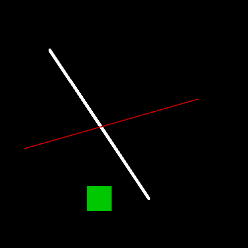
グリフは簡単でもいいのでレンダリングできると圧倒的にテンションが上がります。なのでグリフデータを読み込み始める前に、簡単な2Dレンダラーを作っていきましょう。最初は点、直線、正方形を自由な場所に書き込めれば十分です。
簡単のために、フレームバッファと描写メソッドが一緒になったFrameBufferCanvasクラスを作ります。フレームバッファはピクセルごとのRGB情報を持った1次元配列とします。
まずは描写メソッドを作ります。点の描写はターゲットのピクセルを新しいRGBで更新。直線、正方形は点を与えられた区間に打ち続ければOKです。各点のx,y座標をバラバラに渡すのは後に面倒になるので、ベクトルを受け取れるオーバーロードも用意していると便利です。あとはレンダリング結果を画像にするため、stb-image-writerを使ってpngに出力するメソッドも作っておきます。
直線のアルゴリズムはBresenham’s line drawing - Playing with codeのものを借用しました。エンジニア全員やったほうが良い3Dレンダラー自作チュートリアルです。
FrameBufferCanvasのコード
struct RGB {
  unsigned r, g, b;
  RGB() = default;

  constexpr RGB(const unsigned r_, const unsigned g_,
                const unsigned b_) : r(r_), g(g_), b(b_) {
  }

  constexpr explicit RGB(const unsigned greyscale) : r(greyscale),
    g(greyscale), b(greyscale) {
  }

  bool operator==(const RGB& a) const {
    return r == a.r && g == a.g && b == a.b;
  }
};

FrameBufferCanvas::FrameBufferCanvas(const int width_,
                                     const int height_) :
  width(width_), height(height_) {
  framebuffer = std::make_unique<RGB[]>(width * height);
  for (int i = 0; i < width * height; ++i) framebuffer[i] = BLACK;
}

void FrameBufferCanvas::set(const int x,
                            const int y,
                            const RGB color) {
  if (x < 0 || y < 0) return;
  if (x >= width || y >= height) return;
  const std::size_t i = static_cast<std::size_t>(y) * static_cast<std::size_t>(
                          width) + static_cast<std::size_t>(x);
  framebuffer[i] = color;
}

void FrameBufferCanvas::drawLine(int ax, int ay, int bx, int by,
                                 const int thickness,
                                 const RGB color) {
  const int w = std::abs(ax - bx);
  const int h = std::abs(ay - by);
  const bool isSteep = w < h;
  if (isSteep) {
    std::swap(ax, ay);
    std::swap(bx, by);
  }
  if (ax > bx) {
    std::swap(ax, bx);
    std::swap(ay, by);
  }
  auto y = static_cast<float>(ay);
  for (int x = ax; x <= bx; ++x) {
    if (isSteep) {
      drawRect(static_cast<int>(y), x, thickness, thickness, color);
    } else {
      drawRect(x, static_cast<int>(y), thickness, thickness, color);
    }
    y += static_cast<float>(by - ay) / static_cast<float>(bx - ax);
  }
}

void FrameBufferCanvas::drawRect(const int centerX,
                                 const int centerY,
                                 const int rectWidth,
                                 const int rectHeight,
                                 const RGB color) {
  // compute integer bounds
  const int halfW = rectWidth / 2;
  const int halfH = rectHeight / 2;
  int left = centerX - halfW;
  int top = centerY - halfH;
  int right = left + rectWidth;
  int bottom = top + rectHeight;

  // clip to framebuffer
  if (right <= 0 || bottom <= 0) return;
  if (left >= width || top >= height) return;

  left = std::max(left, 0);
  top = std::max(top, 0);
  right = std::min(right, width);
  bottom = std::min(bottom, height);

  for (int y = top; y < bottom; ++y) {
    for (int x = left; x < right; ++x) {
      set(x, y, color);
    }
  }
}

void FrameBufferCanvas::writePngFile(const char* fileName) const {
  stbi_write_png(fileName, width, height, 3, framebuffer.get(), 0);
}
int main() {
  FrameBufferCanvas canvas{500, 500};
  canvas.drawLine(100, 100, 300, 400, 5, {255, 255, 255});
  canvas.drawLine(400, 200, 50, 300, 2, {200, 0, 0});
  canvas.drawRect(200, 400, 50, 50, {0, 200, 0});
  canvas.writePngFile("out.png");
}
これでグリフを描写する準備ができました。
グリフのパース & アウトラインの描写
それでは本丸、グリフのパースを行っていきます。グリフの情報はglyfテーブルに入っています。グリフにはSimple glyphとCompound glyphの二種類ありますが、Compound glyphは複数のグリフを内包したグリフなため、一旦Simple glyphを読み込むことを目標に進めていきましょう。
glyfテーブルのパース
その他のテーブル同様、glyfテーブルもヘッダと本体の二箇所に分かれています。ヘッダ部で重要な情報はnumberOfContours、輪郭数です。ここが正ならSimple glyphの輪郭数、負ならCompound glyphというように分岐します。
グリフヘッダテーブル
| 型 | 名前 | 説明 |
|---|---|---|
| int16 | numberOfContours | 輪郭の数 プラスならSimple glyph マイナスならCompound glyph |
| FWord | xMin | x座標最小値 |
| FWord | yMin | y座標最小値 |
| FWord | xMax | x座標最大値 |
| FWord | yMax | y座標最大値 |
Simple glyph
本体です。ついにグリフのレンダリングに必要な情報が出てきました!輪郭の最後の点は輪郭の数だけあり、その他の配列は頂点の数だけあるのが注意点です。頂点の数は明示されていませんが、endPtsOfContoursの最大値を取ればOKです。インストラクションは今回の実装では無視します。
Simple glyphテーブル
| 型 | 名前 | 説明 |
|---|---|---|
| uint16 | endPtsOfContours[n] | 輪郭の最後の点のインデックスの配列(n=輪郭数) |
| uint16 | instructionLength | インストラクションの長さ |
| uint8 | instructions[instructionLength] | インストラクション |
| uint8 | flags[variable] | フラグの配列(n=頂点数) |
| uint8 or int16 | xCoordinates[] | x座標(n=頂点数) |
| uint8 or int16 | yCoordinates[] | y座標(n=頂点数) |
ややこしいのがフラグです。いくつかのフラグは他のフラグの挙動を分岐させます。具体的には1,2,4,5ビットの挙動が以下のようになっています。
- 3がセットされていたら次のバイトで示された数分だけ同じフラグを使用する
- 1,2と4,5はそれぞれx, yの座標を得るためのフラグ
- 1,2がセットされていたら、対応する座標の長さは1byte(unsigned)、そうでなければ2bytes(signed)
- 1,2がセットされているとき、4,5は符号になる
- 1,2がセットされておらず、4.5がセットされていれば、一つ前の座標位置と同じ
- 1,2がセットされておらず、4,5もセットされていなければ、2bytes(signed int)が座標位置
On Curveはベジエ曲線を描写するにあたって必要な情報です。後ほど曲線のレンダリングで説明します。Repeatがセットされているときは、すぐ次の16ビットに格納されている数のぶんだけ同じフラグをリピートします。
| フラグ | ビット | 説明 |
|---|---|---|
| On Curve | 0 | オン: 曲線の上 オフ: 曲線の外 |
| x-Short Vector | 1 | オン: x座標が1バイト オフ: x座標が2バイト |
| y-Short Vector | 2 | オン: y座標が1バイト オフ: y座標が2バイト |
| Repeat | 3 | オン: 次の1バイトに入っている数だけ同じフラグが続く オフ: リピートしない |
| This x is same (Positive x-Short vector) | 4 | オン: 2がオンならx座標がプラス、2がオフなら一つ前のx座標と同じ オフ: 2がオンならx座標がマイナス、2がオフならx座標は次のuint16 |
| This y is same (Positive y-Short vector) | 5 | オン: 2がオンならx座標がプラス、2がオフなら一つ前のy座標と同じ オフ: 2がオンなら6座標がマイナス、2がオフならy座標は次のuint16 |
| Reserved | 6 - 7 | 使用されていない |
実装です。グリフには二種類ありますが、GlyphがGlyphComponentを0個以上持つ、という構造にすることで、2種類のグリフで同じ構造を使うことができます。よって実装上、Simple glyphはGlyphComponentを0か1つ持つGlyphになります。getGlyphComponentについてaffineMatを受け取っていますが、これはComponent Glyph用なのでSimple glyphでは単位行列を渡していればOKです。
GlyphとGlyphComponentのヘッダ
struct Metric {
  uint16_t advanceWidth;
  int16_t leftSideBearing;
};

class Glyph {
public:
  Glyph() = default;
  explicit Glyph(std::vector<GlyphComponent> components_, Metric metric_);
  [[nodiscard]] const std::vector<GlyphComponent>& getComponents() const;
  [[nodiscard]] const Metric& getMetric() const;
  static Glyph EmptyGlyph(Metric metric_);

private:
  std::vector<GlyphComponent> components;
  Metric metric;
};
class GlyphComponent {
public:
  GlyphComponent() : numOfVertices(0) {
  }

  explicit GlyphComponent(uint16_t numOfVertices_,
                          std::unordered_set<uint16_t> endPtsOfContours_,
                          std::unordered_set<uint16_t> ptsOnCurve_,
                          BoundingRect boundingRect_,
                          std::vector<glm::vec2> coordinates_);
  [[nodiscard]] uint16_t getNumOfVertices() const;
  [[nodiscard]] BoundingRect getBoundingRect() const;
  [[nodiscard]] const std::unordered_set<uint16_t>& getEndPtsOfContours() const;
  [[nodiscard]] const std::unordered_set<uint16_t>& getPtsOnCurve() const;
  [[nodiscard]] const std::vector<glm::vec2>& getCoordinates() const;

private:
  uint16_t numOfVertices;
  std::unordered_set<uint16_t> endPtsOfContours;
  BoundingRect boundingRect;
  std::vector<glm::vec2> coordinates;
  std::unordered_set<uint16_t> ptsOnCurve;
};
Simple Glyphパーサーのコード
Glyph FontParser::getGlyph(const uint32_t cp) {
  if (!unicodeToGlyphCode.contains(cp)) {
    throw std::runtime_error("Glyph not found");
  }
  return getGlyphByCode(unicodeToGlyphCode[cp]);
}

Glyph FontParser::getGlyphByCode(const uint16_t glyphCode) {
  const auto [numOfContours, boundingRect] = readGlyphHeader(glyphCode);
  Glyph glyph;
  const auto metric = glyphMetric[glyphCode];
  if (numOfContours == 0) {
    // No glyph needed i.e. space
    glyph = Glyph::EmptyGlyph(metric);
  } else if (numOfContours > 0) {  // Read simple glyphs
    glyph = Glyph({getGlyphComponent(numOfContours, boundingRect)},
                  metric);
  } else {
    glyph = getCompoundGlyph(); // Not implemented yet!
  }
  return glyph;
}

GlyphHeader FontParser::readGlyphHeader(const uint16_t glyphCode) {
  const auto offset = glyphCodeToOffset[glyphCode];
  if (offset == 0) {
    return GlyphHeader{0, BoundingRect{0, 0, 0, 0}};
  }

  jumpTo(offset);
  // Read glyph description
  const auto numOfContours = readInt16(); // number of contours
  BoundingRect boundingRect;
  boundingRect.xMin = readInt16();
  boundingRect.yMin = readInt16();
  boundingRect.xMax = readInt16();
  boundingRect.yMax = readInt16();

  return GlyphHeader{numOfContours, boundingRect};
}

GlyphComponent FontParser::getGlyphComponent(
    const int16_t numOfContours,
    const BoundingRect boundingRect,
    const glm::mat3& affineMat) {
  std::unordered_set<uint16_t> endPtsOfContours;

  uint16_t numOfVertices = 1;
  for (int i = 0; i < numOfContours; ++i) {
    const auto point = readUint16();
    numOfVertices = std::max(numOfVertices, static_cast<uint16_t>(point + 1));
    endPtsOfContours.insert(point);
  }
  // Skip instructions
  skipBytes(readUint16());

  std::vector<uint8_t> allFlags(numOfVertices, 0);
  std::unordered_set<uint16_t> ptsOnCurve;
  uint16_t idx = 0;
  while (idx < numOfVertices) {
    const uint8_t f = readUint8();
    allFlags[idx] = f;
    //ON_CURVE_POINT
    if (isFlagSet(f, 0)) ptsOnCurve.insert(idx);
    if (isFlagSet(f, 3)) {
      // REPEAT_FLAG
      const uint8_t repeat = readUint8();
      // fill repeats
      for (uint16_t r = 1; r <= repeat; ++r) allFlags[idx + r] = f;
      idx += static_cast<uint16_t>(repeat) + 1;
    } else {
      ++idx;
    }
  }

  const std::vector<int> xCoordinates = getGlyphCoordinates(
      numOfVertices, allFlags, true);
  const std::vector<int> yCoordinates = getGlyphCoordinates(
      numOfVertices, allFlags, false);
  std::vector<glm::vec2> coordinates;
  for (int i = 0; i < numOfVertices; ++i) {
    const auto coord = affineMat * glm::vec3(xCoordinates[i], yCoordinates[i],
                                             1);
    coordinates.emplace_back(coord.x, coord.y);
  }

  return GlyphComponent{numOfVertices, endPtsOfContours, ptsOnCurve,
                        boundingRect, coordinates};
}

std::vector<int> FontParser::getGlyphCoordinates(const uint16_t& n,
                                                 const std::vector<uint8_t>&
                                                 flags,
                                                 const bool isX) {
  std::vector coordinates(n, 0);
  for (int i = 0; i < n; ++i) {
    const auto f = flags[i];
    const auto isShort = isFlagSet(f, isX ? 1 : 2);
    int pos = coordinates[i == 0 ? 0 : i - 1];

    if (isShort) {
      const auto isPositive = isFlagSet(f, isX ? 4 : 5);
      const auto offset = isPositive
                            ? readUint8()
                            : -1 * static_cast<int>(readUint8());
      pos += offset;
    } else {
      if (!isFlagSet(f, isX ? 4 : 5)) {
        pos += readInt16();
      };
    }

    coordinates[i] = pos;
  }
  return coordinates;
}
アウトラインを直線でレンダリング
それではグリフをパースして得たx,y座標を直線で繋いでみましょう。グリフの座標は直交座標系ですが、フレームバッファは左上が原点の画像座標系なので座標変換を行う必要があります。ここでは一旦出力画像を上下反転しちゃいましょう。ちゃんとした座標変換は後ほど扱います。
グリフのアウトラインを直線でレンダリングするコード
void FrameBufferCanvas::renderGlyphOutline(const unsigned int startX,
                                    const unsigned int startY,
                                    const Glyph& glyph,
                                    const RGB color) {
  for (const auto& c : glyph.getComponents()) {
    uint16_t contourStartPt = 0;
    const auto n = c.getNumOfVertices();
    const auto coordinates = c.getCoordinates();
    const auto endPtsOfContours = c.getEndPtsOfContours();

    for (int i = 0; i < n; ++i) {
      const auto isEndPt = endPtsOfContours.contains(i);
      const auto nextIdx = isEndPt ? contourStartPt : (i + 1) % n;
      const auto x = coordinates[i].x + startX;
      const auto y = coordinates[i].y + startY;
      const auto nextX = coordinates[nextIdx].x + startX;
      const auto nextY = coordinates[nextIdx].y + startY;
      drawLine(x, y, nextX, nextY, 5, color);
      drawRect(x, y, 20, 20, color);
      if (isEndPt) contourStartPt = i + 1;
    }
  }
    stbi_flip_vertically_on_write(1);
}
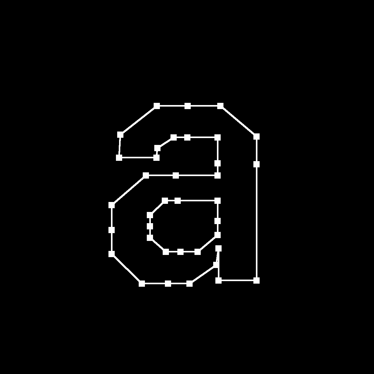
int main() {
  FontParser parser("fonts/JetBrainsMono-Bold.ttf");
  FrameBufferCanvas canvas{1200, 1200};
  const auto cps = utf8ToCodepoints("a");
  const Glyph glyph = parser.getGlyph(cps[0]);
  canvas.renderGlyphOutline(300, 300, glyph, RGB{255});
  canvas.writePngFile("out.png");
}
輪郭がレンダリングできました!まだカクカクしてますが、ここまででも十分感動的だと思いませんか?
Compound glyph
Simple glyphのデータを無事読み込めたなら、それはCompound glyphを扱う準備ができたということです。Compound glyphのアイデア自体は"o"と"ö"、"i"と"j"のようにグリフの一部が同じ形なら、その部分は共通化できるよね、という単純なものです。ただし、グリフを組み合わせるには最終的にできるグリフの中での各要素の位置やサイズ、変形方法を指定する必要があります。それを考慮しないと、以下のような結果になります。
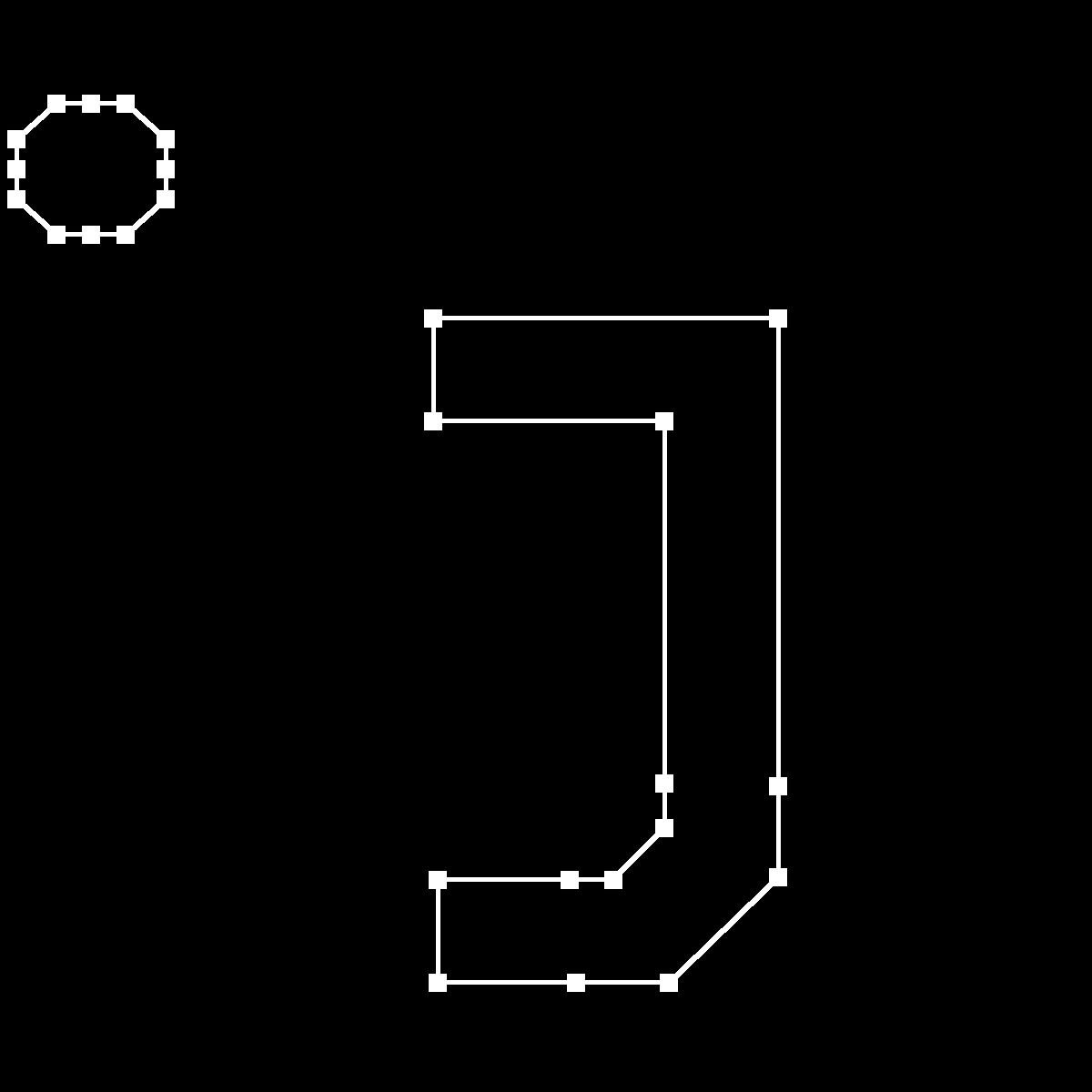
点があらぬ場所にある、jになるはずだったもの
それではCompound glyphのデータをパースしていきます。ここがパーサーで最もややこしいですが、ゆっくり追えば理解できるはずです!
Glyphのヘッダ部はSimple glyphと共通で、numberOfContoursが負のときに本体部分がCompound glyphのものになります。Compound glyph自体にはグリフの座標情報などは入っておらず、Compoundの中に複数のComponent glyphが入っている入れ子構造になっています。そのComponentはSimple glyph, Compound glyphのどちらも取りうるのですが、Simple glyphしか具体的な座標情報を持っていないことから、最終的にはSimple glyphに行き着くようになっています。なので複数のComponentsを取り出して、変形して、合体する必要があるということです。
基本的にはComponentを変形するための式を構築します。どのような式になるのかはフラグによって変わります。そしてそのフラグが多く10個もありますが、この記事ではARGS_ARE_XY_VALUES, ROUND_XY_TO_GRID, WE_HAVE_INSTRUCTIONS, OVERLAP_COMPOUNDの4つは無視することにします。
ここで大事な情報はどうやってこのComponentを変形、移動するかです。仕様書には以下の式が書かれています。
a,b,c,dはフラグによって以下のように定義され、データはパーツテーブルの次に入っています。ここでa,b,c,dはF2Dot14型であることに注意してください。
| WE_HAVE _A_SCALE |
WE_HAVE AN_X_AND Y SCALE |
WE_HAVE_A TWO_BY TWO |
a | b | c | d |
|---|---|---|---|---|---|---|
| 0 | 0 | 0 | 1.0 | 0.0 | 0.0 | 1.0 |
| 1 | 0 | 0 | 1st short | 0.0 | 0.0 | 1st short |
| 0 | 1 | 0 | 1st short | 0.0 | 0.0 | 2nd short |
| 0 | 0 | 1 | 1st short | 2nd short | 3rd short | 4th short |
e,fにはARGS_ARE_XY_VALUESが常にオンと仮定すると変数1, 変数2がそのまま入ります。
そしてWE_HAVE_A_SCALE, WE_HAVE_AN_X_AND_Y_SCALE, WE_HAVE_A_TWO_BY_TWOと先ほどの変数、追加で読み込むいくつかの値によって行列が決定されます。このフラグたちは排他的で同時に複数がオンになることはありません。上のテーブルを読み解くと、各フラグに応じて以下のような変形が行われることがわかります。
- WE_HAVE_A_SCALE: x,yで同じ拡大
- WE_HAVE_AN_X_AND_Y_SCALE scale: x,yで異なる拡大
- WE_HAVE_A_TWO_BY_TWO: 線形変換用の行列がまるっと与えられる
最後に、mはm₀ = max(|a|, |b|), If |(|a|-|c|)| ≤ 33/65536, then m = 2m₀; otherwise, m = m₀で定義され、nについても同様です。
この先は点や線をベクトルで表現していくので、変換を簡単にするために取り出した変数と与えられた式をもとにアフィン変換用の行列をつくりましょう。
行列が完成したのでGlyphComponentを取得するメソッドに渡して、帰ってきたGlyphからComponentを取り出し組み合わせればよいということです。最終的なグリフのMetricはUSE_MY_METRICSがオンのComponentのものを使います。
この一連をMORE_COMPONENTSがオンの限りループして合成していき、最終的なCompound glyphの完成です!
Component glyphパーツテーブル
| 型 | 名前 | 説明 |
|---|---|---|
| uint16 | flags | フラグ |
| uint16 | glyphIndex | 読み込み先のGlyphCode |
| int16, uint16, int8 or uint8 | argument1 | 変数1 フラグによって内容が変わる |
| int16, uint16, int8 or uint8 | argument2 | 変数2 フラグによって内容が変わる |
| transformation option | 変形オプション |
flagsの内容
| フラグ | ビット | 説明 |
|---|---|---|
| ARG_1_AND_2_ARE_WORDS | 0 | オン: 変数1の型がWord オフ: Byte |
| ARGS_ARE_XY_VALUES | 1 | オン: 変数はx,y座標 オフ: アンカーポイント |
| ROUND_XY_TO_GRID | 2 | ビット1がオンのときだけ読む オン: x,yをグリッドに合わせて丸める オフ: 丸めない |
| WE_HAVE_A_SCALE | 3 | オン: 後に与えられる値でスケールする オフ: スケール値を1とする |
| (this bit is obsolete) | 4 | 使われていないフラグ |
| MORE_COMPONENTS | 5 | オン: この次にまだComponentがある オフ: もうない |
| WE_HAVE_AN_X_AND_Y_SCALE | 6 | オン: x座標のスケールがy座標と異なる オフ: x,yどちらも同じスケーリング |
| WE_HAVE_A_TWO_BY_TWO | 7 | オン: 線形変換用の2x2行列が与えられる オフ: 与えられない |
| WE_HAVE_INSTRUCTIONS | 8 | オン: インストラクションがある オフ: ない |
| USE_MY_METRICS | 9 | オン: このComponentのmetricをCompound glyphのmetricとする オフ: しない |
| OVERLAP_COMPOUND | 10 | オン: このCompound glyphはcomponentsがオーバーラップしてできている オフ: オーバーラップがない |
実装です。Compound glyphが入れ子になっているため再帰を使うと簡単になると思います。
Compound Glyphパーサーのコード
std::vector<GlyphComponent> FontParser::getCompoundSubComponents(
    const uint16_t glyphCode,
    const glm::mat3& affineMat) {
  const auto [numOfContours, boundingRect] = readGlyphHeader(glyphCode);
  std::vector<GlyphComponent> components;
  if (numOfContours > 0) {
    // Simple
    components.emplace_back(
        getGlyphComponent(numOfContours, boundingRect, affineMat));
  } else {
    // Compound: Compound glyph can have nested Compound glyphs
    const auto subComponents = getCompoundGlyph().getComponents();
    components.insert(components.begin(), subComponents.begin(),
                      subComponents.end());
  }
  return components;
}

Glyph FontParser::getCompoundGlyph() {
  std::vector<GlyphComponent> components;
  uint16_t flags;
  Metric metric{};
  do {
    flags = readUint16();
    const uint16_t glyphCode = readUint16();
    // read flags
    const bool isWord = isFlagSet(flags, 0);
    const bool isXyValue = isFlagSet(flags, 1); // not implemented
    const bool roundXyGrid = isFlagSet(flags, 2); // not implemented
    const bool hasScale = isFlagSet(flags, 3);
    const bool hasXScale = isFlagSet(flags, 6);
    const bool hasTwoByTwo = isFlagSet(flags, 7);
    const bool hasInstruction = isFlagSet(flags, 8); // not implemented
    const bool useMetrics = isFlagSet(flags, 9);
    const bool overlap = isFlagSet(flags, 10); // not implemented

    // read arguments (arg1,arg2) either words or bytes (signed)
    int32_t arg1 = 0, arg2 = 0;
    if (isWord) {
      arg1 = readInt16();
      arg2 = readInt16();
    } else {
      arg1 = static_cast<int32_t>(static_cast<unsigned char>(readInt8()));
      arg2 = static_cast<int32_t>(static_cast<unsigned char>(readInt8()));
    }
    // interpret arg1/arg2 later: XY values
    const int32_t e_raw = arg1;
    const int32_t f_raw = arg2;

    // read transform values only when indicated
    double a = 1.0, b = 0.0, c = 0.0, d = 1.0;
    if (hasScale) {
      const double s = readF2Dot14();
      a = d = s;
      b = c = 0.0;
    } else if (hasXScale) {
      a = readF2Dot14();
      d = readF2Dot14();
      b = c = 0.0;
    } else if (hasTwoByTwo) {
      a = readF2Dot14();
      b = readF2Dot14();
      c = readF2Dot14();
      d = readF2Dot14();
    } // else identity

    // Normalization factors    constexpr float eps = 33.0 / 65536.0;
    float m = static_cast<float>(std::max(std::fabs(a), std::fabs(b)));
    m = std::fabs(a) - std::fabs(c) <= eps ? 2 * m : m;
    float n = static_cast<float>(std::max(std::fabs(c), std::fabs(d)));
    n = std::fabs(b) - std::fabs(d) <= eps ? 2 * n : n;
    const auto e = static_cast<float>(e_raw);
    const auto f = static_cast<float>(f_raw);

    // The affine transformation matrix, looks like this:
    // [a, c, me]
    // [b, d, nf]
    // [0, 0,  1]
    const auto affineMat = glm::mat3(a, b, 0, c, d, 0, m * e, n * f, 1);

    // Needs to save the current reader pos since getGlyph jumps to a certain offset pos
    const auto currentOffset = ifs.tellg();
    const auto subComponents =
        getCompoundSubComponents(glyphCode, affineMat);
    if (subComponents.empty()) {
      throw std::runtime_error(
          "FontParser: Something went wrong with loading component glyphs");
    }
    components.insert(components.end(), subComponents.begin(),
                      subComponents.end());

    if (useMetrics) {
      metric = glyphMetric[glyphCode];
    }
    // Reload the prev reader pos for the next loop
    jumpTo(currentOffset);
  } while (isFlagSet(flags, 5)); // MORE_COMPONENTS

  return Glyph(components, metric);
}
これで最低限のTrueTypeパーサーが完成しました。"j"もちゃんとレンダリングされています!
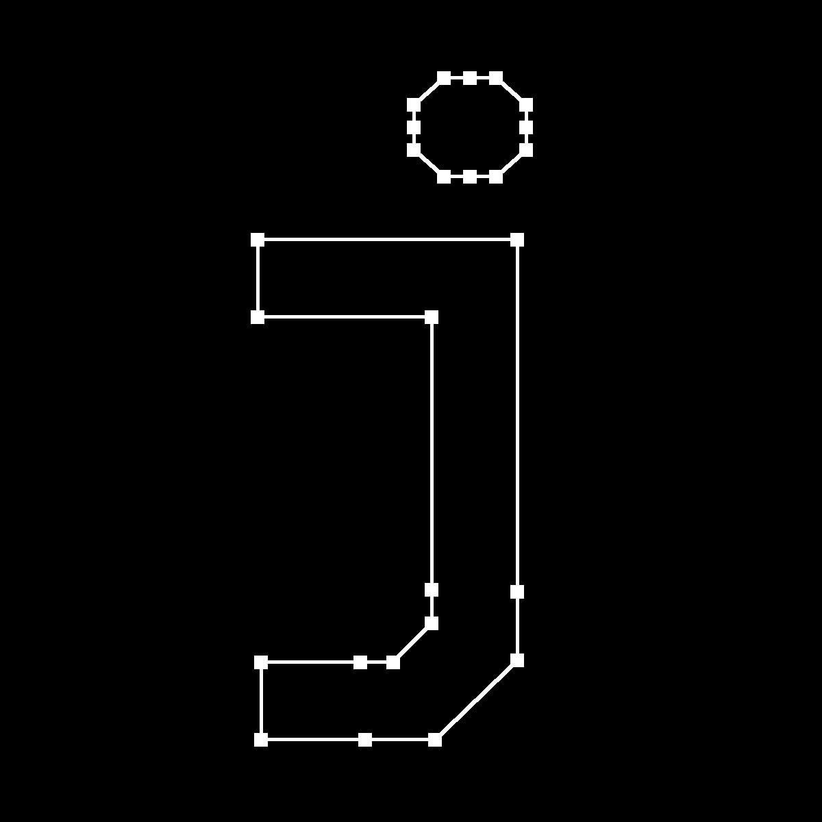
点を取り戻したjくん
レンダラー 曲線の描写
次はレンダラーを改善していきましょう。まずは曲線を描写したいですね。
ベジエ曲線の定義
ベジエ曲線は多くのベクターグラフィックで用いられている、数式で表されるなめらかな曲線です。ベクターグラフィックスエディタでよく見かけると思います。
先述の通り、TrueTypeの曲線は二次ベジエ曲線で表されます。よって上の式を展開すると、以下のようになります。
余裕のある方は以下のオンラインブックを読んでみると良いと思います。
ド・カステリョのアルゴリズム
ここで、ベジエ曲線には「制御点を
コードに起こしてみるとこうなります。
inline glm::vec2 lerp(const glm::vec2& a, const glm::vec2& b, const float t) {
  assert(t >= 0 && t <= 1);
  return a + (b - a) * t;
}

inline glm::vec2
bezierLerp(const glm::vec2& a, const glm::vec2& b, const glm::vec2& c,
           const float t) {
  assert(t >= 0 && t <= 1);
  return lerp(lerp(a, b, t), lerp(b, c, t), t);
}
TrueTypeのベジエ曲線
グリフをパースしたとき、Simple Glyphの各点にON_CURVE_POINTフラグがあったのを覚えていますか?実はこのフラグが曲線の端点かどうかを表す値だったのです。フラグがオンのとき、ベジエ曲線のカーブ上にある、つまり線分の端点で、オフのときは端点以外の制御点になります。
このセクションの以降の説明では、簡単のために端点を

レンダリング結果を眺めていると、ある違和感に気づくかもしれません。
- "
A B A - "
B B B A
これを踏まえて、

ちゃんと曲線部では端点とそれ以外が交互に現れていますね!それでは以上を踏まえて実装用にフローを整理しましょう。
- ひとつ前に描写につかった
A \text{prev}A - 今見ている点が
A A - 今見ている点が
B - グリフデータ上の次の点も
B A^\prime \text{prev}A B A^\prime - グリフデータ上の次の点が
A \text{prev}A B A
- グリフデータ上の次の点も
ちょうどよいので、ここで座標変換用のアフィン変換行列を用意して、グリフの開始x座標も簡単に渡せるようにしましょう。まずは座標系をx軸に対して反転させる行列を作っておいて、後からベースラインとグリフのx座標を調整できるようにします。
ベジエ曲線の処理を加えたアウトラインレンダラーのコード
void FrameBufferCanvas::setGlyphBaseline(const int baseline) {
  transformMat[2][1] += baseline;
}

void FrameBufferCanvas::renderGlyphOutline(const Glyph& glyph,
                                           const RGB color,
                                           const int startX,
                                           const int thickness) {
  for (const auto& c : glyph.getComponents()) {
    const auto rectSize = thickness * 2;
    uint16_t contourStartPt = 0;
    const auto n = c.getNumOfVertices();
    const auto coordinates = c.getCoordinates();
    const auto endPtsOfContours = c.getEndPtsOfContours();
    const auto ptsOnCurve = c.getPtsOnCurve();

    transformMat[2][0] = startX;

    // Cache of point vectors of vertices
    std::unordered_map<int, glm::vec2> points;
    for (int i = 0; i < n; ++i) {
      // Convert coordinate system from bottom-up to top-down
      points[i] = transformVec2(transformMat, coordinates[i]);
    }

    auto prevPt = glm::vec2(0.f);
    for (int i = 0; i < n; ++i) {
      const auto isEndPt = endPtsOfContours.contains(i);
      const auto nextIdx = isEndPt ? contourStartPt : (i + 1) % n;
      const auto isOnCurve = ptsOnCurve.contains(i);
      const auto isNextOnCurve = ptsOnCurve.contains(nextIdx);
      // Convert coordinate system from bottom-up to top-down
      auto currentPt = points[i];
      auto nextPt = points[nextIdx];

      if (isOnCurve) {
        if (isNextOnCurve) {
          drawLine(currentPt, nextPt, thickness, color);
        }
        prevPt = currentPt;
      } else {
        if (!isNextOnCurve) {
          // Calculate the implicit next "on-curve" from the middle point of next control point
          nextPt = (currentPt + nextPt) / 2.0f;
        }
        drawBezier(prevPt, currentPt, nextPt, thickness, color);
        // Draw implicit next on-curve point
        drawRect(nextPt, rectSize, rectSize, BLUE);
        prevPt = nextPt;
      }
      drawRect(currentPt, rectSize, rectSize, isOnCurve ? RED : GREEN);
      if (isEndPt) contourStartPt = i + 1;
    }
  }
}


void FrameBufferCanvas::drawBezier(const glm::vec2& startPt,
                                   const glm::vec2& midPt,
                                   const glm::vec2& endPt,
                                   const int thickness,
                                   const RGB color) {
  // approximate curve length
  const float approxLen = glm::length(midPt - startPt) + glm::length(
                              endPt - midPt);
  const int res = std::max(1, static_cast<int>(std::ceil(approxLen)));

  glm::vec2 last = startPt;
  for (int i = 1; i <= res; ++i) {
    const float t = static_cast<float>(i) / static_cast<float>(res);
    glm::vec2 cur = quadBezierLerp(startPt, midPt, endPt, t);
    drawLine(last, cur, thickness, color);
    last = cur;
  }
}
これでアウトラインまでレンダリングできました!

レンダラー グリフの塗りつぶし
最後の関門、塗りつぶしです。TrueTypeにはグリフのアウトラインのデータまでしか無く、塗りつぶし方法は各レンダラーの実装次第になっています。今回はベクターデータの塗りつぶし方式として一般的な、Even-odd法とNon-zero法の二種類を実装してみます。

左: Even-odd法での塗りつぶし 右: Non-zero法での塗りつぶし
Even-odd法
任意の点から任意の方向に直線(スキャンライン)を引き、その直線が図形の輪郭と交わった回数が偶数回なら塗らない、奇数回なら塗る、というシンプルなアルゴリズムです。したがって、直線と線分、直線と曲線が交差する点を返す関数を作れば良いということです。
線分の交点
線分の交差判定は領域を使うと少し楽ですね。線分
直線
これを変形して、
交点があることがわかったら、ベクトルを用いて交点の座標を求めます。
とおくと、
よって、
ふたつの線分の交点を求めるコード
inline std::optional<glm::vec2> segmentsIntersect(
    const glm::vec2& a1, const glm::vec2& a2,
    const glm::vec2& b1, const glm::vec2& b2) {
  //  >0: c is above of start-end line, <0: below, ==0: on the line
  const auto region = [](const glm::vec2& pt, const glm::vec2& start,
                         const glm::vec2& end) {
    return (end.y - start.y) * (pt.x - start.x) - (end.x - start.x) * (
             pt.y - start.y);
  };
  const auto ra = region(b1, a1, a2) * region(b2, a1, a2) <= 0;
  const auto rb = region(a1, b1, b2) * region(a2, b1, b2) <= 0;

  if (ra && rb) {
    const glm::vec2 v1 = a2 - a1;
    const glm::vec2 v2 = b2 - b1;

    // 2D scalar cross product
    auto cross = [](const glm::vec2& u, const glm::vec2& v) {
      return u.x * v.y - u.y * v.x;
    };

    const auto denom = cross(v1, v2);
    if (std::fabs(denom) < eps) return std::nullopt;
    // parallel / numeric guard

    const auto t = cross(b1 - a1, v2) / denom;
    return a1 + t * v1;
  }
  return std::nullopt;
}
ベジエ曲線の交差判定
次はベジエ曲線と線分の交点を求めます。二次方程式の解の公式が使えるので、代入して直接交点の
ここで先程登場した直線のベクトル方程式について、
この
で、代入後の二次方程式は以下の通り。
あとはこれを解いて
線分とベジエ曲線の交点を求めるコード
inline std::vector<glm::vec2> segmentQuadBezierIntersect(
    const glm::vec2& p1, // bezier start
    const glm::vec2& p2, // bezier control
    const glm::vec2& p3, // bezier end
    const glm::vec2& l1, // line start
    const glm::vec2& l2 // line end
    ) {
  const auto k = glm::vec2((l2 - l1).y, -(l2 - l1).x);
  const auto a = p3 - 2.0f * p2 + p1;
  const auto b = 2.0f * (p2 - p1);
  const auto c = p1;

  const auto ts = solveQuadratic(
      dot(k, a),
      dot(k, b),
      dot(k, c - l1)
      );

  std::vector<glm::vec2> intersects(0);
  for (const auto t : ts) {
    if (-eps <= t && t <= 1.0f + eps)
      intersects.push_back(
          a * t * t + b * t + c);
  }
  return intersects;
}

ちなみに解析的に出す方法は解の公式がまともに使える二次ベジエ曲線までしか使えません。Bezier clippingという数値的に出す手法なら、より高次のベジエ曲線でも高速に判定できるようです。
交点を求める関数ができたので、塗りつぶしを実装していきます。
Even-odd法での塗りつぶしを行うコード
void FrameBufferCanvas::renderGlyphByEvenOdd(const Glyph& glyph,
                                             const RGB color,
                                             const int startX) {
  // Loop for each glyph components
  for (const auto& c : glyph.getComponents()) {
    const auto n = c.getNumOfVertices();
    const auto coordinates = c.getCoordinates();
    const auto endPtsOfContours = c.getEndPtsOfContours();
    const auto ptsOnCurve = c.getPtsOnCurve();

    transformMat[2][0] = startX;

    // Cache of point vectors of vertices
    std::unordered_map<int, glm::vec2> points;
    for (int i = 0; i < n; ++i) {
      // Convert coordinate system from bottom-up to top-down
      points[i] = transformVec2(scale * transformMat, coordinates[i]);
    }

    // Loop for each scanline
    auto rayStart = glm::vec2(0, 0);
    auto rayEnd = glm::vec2(width, 0);
    for (int y = 0; y < height; ++y) {
      rayStart.y = rayEnd.y = static_cast<float>(y);
      std::vector<int> intersections;
      uint16_t contourStartPt = 0;
      auto prevPt = glm::vec2(0.f);
      // Loop for each vertex
      for (int i = 0; i < n; ++i) {
        const auto isEndPt = endPtsOfContours.contains(i);
        const auto nextIdx = isEndPt ? contourStartPt : (i + 1) % n;
        const auto isOnCurve = ptsOnCurve.contains(i);
        const auto isNextOnCurve = ptsOnCurve.contains(nextIdx);
        auto currentPt = points[i];
        auto nextPt = points[nextIdx];

        if (isOnCurve) {
          if (isNextOnCurve) {
            // on curve - on curve: Straight line
            const auto s = segmentsIntersect(
                currentPt, nextPt, rayStart, rayEnd);
            if (s) {
              intersections.emplace_back(static_cast<int>(s.value().x));
            }
          }
          prevPt = currentPt;
        } else {
          // not on curve: Control point
          if (!isNextOnCurve) {
            // Calculate the implicit next "on-curve" from the middle point of next control point
            nextPt = (currentPt + nextPt);
            nextPt /= 2;
          }
          const auto ss = segmentQuadBezierIntersect(
              prevPt,
              currentPt,
              nextPt,
              rayStart,
              rayEnd
              );
          for (const auto s : ss) {
            intersections.emplace_back(static_cast<int>(s.x));
          }
          prevPt = nextPt;
        }
        if (isEndPt) contourStartPt = i + 1;
      }

      std::sort(intersections.begin(), intersections.end());
      int cnt = 0;
      int prevX = 0;
      for (const auto x : intersections) {
        if (cnt % 2 == 1) {
          drawLine(prevX, y, x, y, 1, color);
        }
        cnt++;
        prevX = x;
      }
    }
  }
}

おしい!ほぼほぼ塗りつぶされていますが、妙な線が現れています。2つの線分もしくは曲線が端点を共有するときにエラーが発生しているみたいです。詳しく見てみると、以下の2パターンで間違った塗りが起きていることがわかりました。同じ座標に交点があったとき、2つとも交点としてカウントしたい場合と無視したいケースがあるということです。
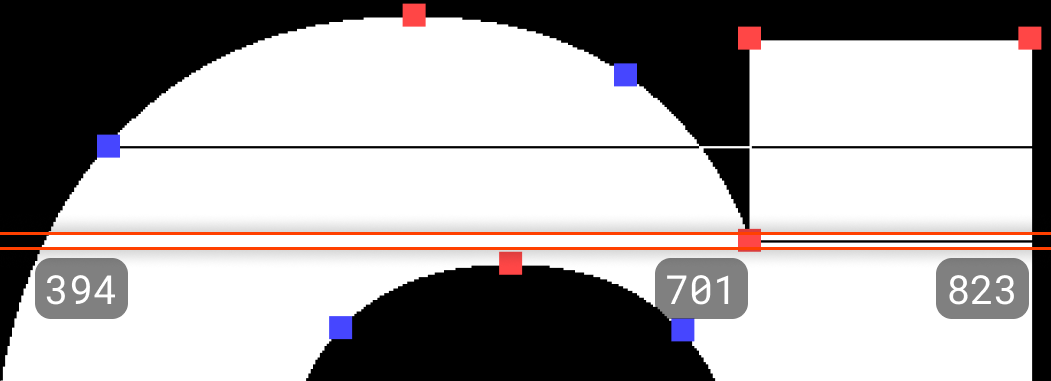
例えば以下画像の上のエラーでは、左からx座標421, 421, 679, 701, 823の5つの交点がカウントされており、421 - 421の線分が描写されたことでそれ以降が反転してしまっています。

カウントしすぎ
翻って、以下のパターンでは左からx座標394, 701, 823の3点のみカウントされていて、線分は394 - 701の間のみ描写されています。本来は左からx座標394, 701, 701, 823か394, 823のようにカウントされるべきです。
カウントたりない
塗りつぶしエラーの除去
これらのような一見一貫性のない挙動について、統一的に判定できる方法はあるでしょうか?まずは問題を単純にするために、どんなときにダブルカウントしてほしいか、もしくはしてほしくないかを、一旦まっすぐな線分で考察してみます。
2つの線分
- スキャンラインより上か下どちらか一方に
A B - スキャンラインの上下に
A B
上下に分かれているときは2つの線分を一つの線分としてみなすイメージで、端点を共有していてもそこでダブルカウントされるべきではないということです。
線分の最小値がスキャンラインよりも小さいときのみ交点をカウントすると、上2つの条件をクリアできそうです。
厳密には、この方法では両端点がスキャンラインよりも下にある場合、1ピクセル分描写されなくなるため完璧な解法ではありませんが、エラーは除去されるため一旦この方法を採用します。

次に、曲線について考えてみましょう。基本的には直線と同じですが、以下のパターンを追加で考慮する必要があります。
- 曲線の端点がスキャンラインより下にあるが、曲線の一部が上にあるときはカウントする
- 曲線の端点がスキャンラインより上にあるが、曲線の一部が下にあるときは無視する

これのチェックを単純に行うには曲線の最小値を求められれば良さそうです。二次ベジエ曲線は先述の通り二次方程式で表せるので、極小時点のパラメータ
以下のようにおいて微分すると、
この
ベジエ曲線の最小値を求めるコード
inline int getBezierMinY(
    const glm::vec2& p1, // bezier start
    const glm::vec2& p2, // bezier control
    const glm::vec2& p3 // bezier end
    ) {
  const auto a = p1.y - 2 * p2.y + p3.y;
  const auto b = 2 * (p2.y - p1.y);

  if (fabs(a) < eps) {
    if (fabs(b) < eps) return static_cast<int>(p1.y);
    return static_cast<int>(std::min(p1.y, p3.y));
  }
  // find the parameter when the curve reaches its extremum by taking the derivative
  const auto t = -b / (2.0f * a);
  // if the curve is convex upwards, the extremum can be the minimum y
  if (-eps <= t && t <= 1.0f + eps && a > 0) {
    return static_cast<int>(a * t * t + b * t + p1.y);
  }
  return static_cast<int>(std::min(p1.y, p3.y));
}
最後に、上の画像の下に凸の場合を確認します。スキャンラインが曲線のどちらかの端点と同じy座標であり、スキャンラインと曲線が2つの交点を持ち、曲線が下に凸の場合、y座標がスキャンラインと同じ方の端点のカウントを無視すればOKです。これできれいに塗りつぶすことができました!
線分と線分の交点で発生するエラーを修正したコード
void FrameBufferCanvas::renderGlyphByEvenOdd(const Glyph& glyph,
                                             const RGB color,
                                             const int startX) {
  // Loop for each glyph components
  for (const auto& c : glyph.getComponents()) {
    const auto n = c.getNumOfVertices();
    const auto coordinates = c.getCoordinates();
    const auto endPtsOfContours = c.getEndPtsOfContours();
    const auto ptsOnCurve = c.getPtsOnCurve();

    transformMat[2][0] = startX;

    // Cache of point vectors of vertices
    std::unordered_map<int, glm::vec2> points;
    for (int i = 0; i < n; ++i) {
      // Convert coordinate system from bottom-up to top-down
      points[i] = transformVec2(scale * transformMat, coordinates[i]);
    }

    // Loop for each scanline
    auto rayStart = glm::vec2(0, 0);
    auto rayEnd = glm::vec2(width, 0);
    for (int y = 0; y < height; ++y) {
      rayStart.y = rayEnd.y = static_cast<float>(y);
      std::vector<int> intersections;
      uint16_t contourStartPt = 0;
      auto prevPt = glm::vec2(0.f);
      // Loop for each vertex
      for (int i = 0; i < n; ++i) {
        const auto isEndPt = endPtsOfContours.contains(i);
        const auto nextIdx = isEndPt ? contourStartPt : (i + 1) % n;
        const auto isOnCurve = ptsOnCurve.contains(i);
        const auto isNextOnCurve = ptsOnCurve.contains(nextIdx);
        auto currentPt = points[i];
        auto nextPt = points[nextIdx];

        if (isOnCurve) {
          if (isNextOnCurve) {
            // on curve - on curve: Straight line
            const auto s = segmentsIntersect(
                currentPt, nextPt, rayStart, rayEnd);
            const auto minY = static_cast<int>(std::min(currentPt.y, nextPt.y));
            if (s && minY < y) {
              intersections.emplace_back(static_cast<int>(s.value().x));
            }
          }
          prevPt = currentPt;
        } else {
          // not on curve: Control point
          if (!isNextOnCurve) {
            // Calculate the implicit next "on-curve" from the middle point of next control point
            nextPt = (currentPt + nextPt);
            nextPt /= 2;
          }
          const auto ss = segmentQuadBezierIntersect(
              prevPt,
              currentPt,
              nextPt,
              rayStart,
              rayEnd
              );
          const auto minY = getBezierMinY(prevPt, currentPt, nextPt);
          if (ss.size() == 2 &&
              !isBezierConvexUpwards(prevPt, currentPt, nextPt)) {
            if (y == static_cast<int>(prevPt.x) || y == static_cast<int>(nextPt.
                  x)) {
              if (static_cast<int>(ss[0].x) == static_cast<int>(prevPt.x)) {
                intersections.emplace_back(static_cast<int>(ss[1].x));
              } else {
                intersections.emplace_back(static_cast<int>(ss[0].x));
              }
            }
          } else if (minY < y) {
            for (const auto s : ss) {
              intersections.emplace_back(static_cast<int>(s.x));
            }
          }
          prevPt = nextPt;
        }
        if (isEndPt) contourStartPt = i + 1;
      }

      std::sort(intersections.begin(), intersections.end());
      int cnt = 0;
      int prevX = 0;
      for (const auto x : intersections) {
        if (cnt % 2 == 1) {
          drawLine(prevX, y, x, y, 1, color);
        }
        cnt++;
        prevX = x;
      }
    }
  }
}

Non-zero法
Even-odd法はシンプルなアルゴリズムな一方、以下のように輪郭が重なっているときに穴が空いてしまいます。

これを改善する方法のひとつに、Non-zero法があります。Non-zero法は基本的にEven-odd法と同じでスキャンラインを使って輪郭と交差する点を見ていきますが、交差回数の偶奇ではなく、スキャンラインが跨いだ輪郭をなす線の向きが上向きなら+1、下向きなら-1としてカウントしていき、0より大きいときに塗ることで穴を発生させずに塗りつぶせる、というアルゴリズムです。グリフの輪郭をなす頂点は右回りもしくは左回りに並んでいるのでそれを利用します。ちなみにブラウザでのsvgのデフォルトの塗りつぶしにはnon-zero法が用いられています。
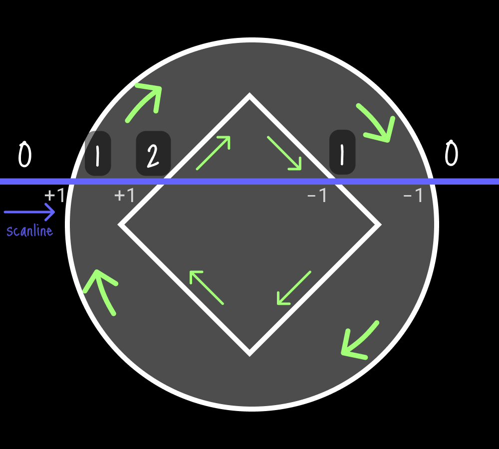
一旦線分だけ考慮して実装してみましょう。Even-oddの交差回数カウントの代わりに以下の処理に入れ替えます。
-
currentPt.y > nextPt.yのとき、isUpwardを交差点に付与する -
isUpwardが0より大きい区間だけ塗りつぶす
線の向きを考慮したレンダリングのコード
...
if (isOnCurve) {
  if (isNextOnCurve) {
    // on curve - on curve: Straight line
    const auto s = segmentsIntersect(
        currentPt, nextPt, rayStart, rayEnd);
    const auto minY = static_cast<int>(std::min(currentPt.y, nextPt.y));
    if (s && minY < y) {
      intersections.emplace_back(
          static_cast<int>(s.value().x),
          currentPt.y > nextPt.y);
    }
  }
  prevPt = currentPt;
}
...
int prevCount = 0;
int prevX = 0;
int count = 0;
for (const auto& [x, isUpward] : intersections) {
  isUpward ? ++count : --count;
  if (prevCount > 0 && count >= 0) {
    drawLine(prevX, y, x, y, 1, WHITE);
  }
  prevCount = count;
  prevX = x;
}
直線だけで構成されているグリフで比較すると、ばっちり塗りつぶせています!

Even-odd法では穴ぼこだったグリフが

綺麗に塗りつぶされた
曲線があっても実はほぼほぼ問題なく塗れていますが、以下のように一部うまく行かないケースがあります。

右下のエラー箇所の線分は{x: 713, isUpwards: true}, {x: 902, isUpwards: false}としてintersectionsに追加されていて問題ありませんし、線分の端点上で発生しているわけではなさそうです。よーく見ると右下のエラー箇所と同じy座標の左下にもエラーがあって、実はここが原因でした。ちょっと分かりづらいですが、左下の本当はもう少しだけ上にカーブが続くはずの部分が描写されていないことがわかります。
ここでの問題はスキャンラインと曲線で交点が2つある場合の線の向きの判定です。曲線の端点のy座標どうしを比較しても2つの交点がそれぞれどちら向きかがわからないため、正しくカウントされずエラーになっていたのでした。このケースでは、以下の図のようにカウントすればうまくレンダリングできそうです。

スキャンラインと曲線が2つの交点を持つ場合の2パターン
この図を眺めてみると、曲線が上下どちらに凸かと、線分のスタートの場所の2要素で判定できることが分かります。
- 上に凸のとき、線分のスタートに近い側の交点は上向き、もう一方は下向き
- 下に凸のとき、線分のスタートに近い側の交点は下向き、もう一方は上向き
思いの外簡単なチェックで曲線の問題をカバー出来ました!
ベジエ曲線がスキャンラインと2つの交点を持つ場合を修正したコード
rvoid FrameBufferCanvas::renderGlyphByNonZero(const Glyph& glyph,
                                             const RGB color,
                                             const int startX) {
  // Loop for each glyph components
  for (const auto& c : glyph.getComponents()) {
    const auto n = c.getNumOfVertices();
    const auto coordinates = c.getCoordinates();
    const auto endPtsOfContours = c.getEndPtsOfContours();
    const auto ptsOnCurve = c.getPtsOnCurve();
    const auto rect = c.getBoundingRect();

    transformMat[2][0] = startX;

    // Cache of point vectors of vertices
    std::unordered_map<int, glm::vec2> points;
    for (int i = 0; i < n; ++i) {
      // Convert coordinate system from bottom-up to top-down
      points[i] = transformVec2(scale * transformMat, coordinates[i]);
    }
    auto rayStart = glm::vec2(0, 0);
    auto rayEnd = glm::vec2(width, 0);

    // Transform the coordinate of the bounding rect
    const auto top = transformVec2(
        scale * transformMat, glm::vec2(0, rect.yMax)).y;
    const auto bottom = transformVec2(
        scale * transformMat, glm::vec2(0, rect.yMin)).y;
    for (int y = top; y < bottom; ++y) {
      rayStart.y = rayEnd.y = static_cast<float>(y);
      std::vector<Intersection> intersections;
      uint16_t contourStartPt = 0;
      auto prevPt = glm::vec2{0, 0};
      // Loop for each vertex
      for (int i = 0; i < n; ++i) {
        const auto isEndPt = endPtsOfContours.contains(i);
        const auto nextIdx = isEndPt ? contourStartPt : (i + 1) % n;
        const auto isOnCurve = ptsOnCurve.contains(i);
        const auto isNextOnCurve = ptsOnCurve.contains(nextIdx);
        auto currentPt = points[i];
        auto nextPt = points[nextIdx];

        if (isOnCurve) {
          if (isNextOnCurve) {
            // on curve - on curve: Straight line
            const auto s = segmentsIntersect(
                currentPt, nextPt, rayStart, rayEnd);
            const auto minY = static_cast<int>(std::min(currentPt.y, nextPt.y));
            if (s && minY < y) {
              intersections.emplace_back(
                  static_cast<int>(s.value().x),
                  currentPt.y > nextPt.y);
            }
          }
          prevPt = currentPt;
        } else {
          // not on curve: Control point
          if (!isNextOnCurve) {
            // Calculate the implicit next "on-curve" from the middle point of next control point
            nextPt = (currentPt + nextPt);
            nextPt /= 2;
          }
          // bezier line
          const auto ss = segmentQuadBezierIntersect(
              prevPt,
              currentPt,
              nextPt,
              rayStart,
              rayEnd
              );

          const auto minY = getBezierMinY(prevPt, currentPt, nextPt);
          if (minY < y) {
            if (ss.size() == 1) {
              intersections.emplace_back(static_cast<int>(ss[0].x),
                                         prevPt.y > nextPt.y);
            } else if (ss.size() == 2) {
              auto nearestX = [&](const glm::vec2& pt) -> int {
                return static_cast<int>((std::fabs(pt.x - ss[0].x) <
                                         std::fabs(pt.x - ss[1].x))
                                          ? ss[0].x
                                          : ss[1].x);
              };
              const int closeXtoCur = nearestX(prevPt);
              const int closeXtoNxt = nearestX(nextPt);
              const auto convexUpwards = isBezierConvexUpwards(
                  prevPt, currentPt, nextPt);
              intersections.emplace_back(closeXtoCur, convexUpwards);
              intersections.emplace_back(closeXtoNxt, !convexUpwards);
            }
          }
          prevPt = nextPt;
        }
        if (isEndPt) contourStartPt = i + 1;
      }

      std::sort(intersections.begin(), intersections.end(),
                [](const Intersection& a, const Intersection& b) {
                  return a.x < b.x;
                });
      int prevCount = 0;
      int prevX = 0;
      int count = 0;
      for (const auto& [x, isUpward] : intersections) {
        isUpward ? ++count : --count;
        if (prevCount > 0 && count >= 0) {
          drawLine(prevX, y, x, y, 1, color);
        }
        prevCount = count;
        prevX = x;
      }
    }
  }
}

文句なし!
これで自作のTrueTypeパーサーとレンダラーで任意の文字列を表示できるようになりました。お疲れ様でした!!

おわりに
まずは長大な記事を最後まで読んで頂きありがとうございました!バイトを一つずつ読み込み、1ピクセルの描写から始めることで、普段意識しないフォントや2Dレンダリングの世界で何が起こっているのか大筋を理解することが出来たと思います。
この記事で作ったパーサーやレンダラーは本当に最低限の機能しかなく、TrueTypeにはまだまだ面白いトピックが詰まっています。例えばヒンティングは、低解像度環境でのリーダビリティを改善するためにグリフ位置を微調整するための技術です。他にもカーニング、合字、縦書きもありますね。アンチエイリアスも大きなトピックです。今回のレンダリングではパフォーマンスを考慮しませんでしたが、GPUを使ったレンダリングの並列化や、GPUに最適化したスキャンラインとは全く異なるアルゴリズムもあります。これらに興味を持たれたら、ぜひとも自分で作って理解してみてください!
参考文献
Fonts - TrueType Reference Manual - Apple Developer
TrueType fundamentals (OpenType 1.9.1) - Typography | Microsoft Learn
Tutorial — FontForge 20230101 documentation
TrueType - Wikipedia
フォント TrueType 構造解析 - yonewiki
Software rendering in 500 lines of bare C++ - Playing with code
ベジェ曲線入門
線形補間 - Wikipedia
nishitalab.org/user/nis/cdrom/cad/CAGD90Curve.pdf
Even–odd rule - Wikipedia
Nonzero-rule - Wikipedia
Discussion