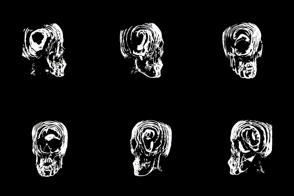
TouchDesingerでTexture3Dを使用してCTスキャンデータを可視化する
この記事はTouchDesigner Advent Calendar 2024の7日目の記事です
はじめに
医療機関でCTやMRIでの撮影を行った際に,CDなどの媒体に保存されたデータをもらえることがあります.CTスキャンではdcmファイルという,デプス方向の次元を持った数百枚の画像データとして保存されており,WebGLやUnityで読み込んで可視化する記事が複数報告されてきました.今回の記事ではTouchDesingerでの読み込み方法と,それを用いたレイマーチングによるボリュームデータの可視化方法をまとめておきます.

サンプルファイル
サンプルファイルは以下からダウンロード可能です.「1. DCMファイルの入手」と「2. pydicomのインストール」を実行すれば動くはずです.
1. DCMファイルの入手
手元にdcmデータがない場合のために,インターネットから利用可能なデータの入手について解説します.
-
https://www.pcir.org/researchers/54879843_20060101.html
- このリンクからデータをダウンロードして解凍する
- 解凍されたデータの中には,「Series 003 [CT - Crane Osseux]」などの名前でdcmファイルが格納されたフォルダがある
- 後の処理ではデータの読み込みでこのフォルダのパスを指定するが,そのままだとパスに含まれた特殊記号でエラーが出るので場所を変更し,フォルダの名前も変更する
- 任意の場所で大丈夫だが,今回は「D:\Downloads\Series 003」とした
2. pydicomのインストール
dcmデータを読み込むために,Pythonのパッケージの一つであるpydicomを使用します.のちのTouchDesinger上でも,ここでインストールしたpydicomを使用して読み込みを行います.
- Pythonの環境を整える
-
https://github.com/pydicom/pydicom
- pydicomのレポジトリ
- Anacondaのdicom環境を作成して,サンプルの実行に必要なnumpyとmatplotlibもインストールしておく
conda install -c conda-forge pydicom numpy matplotlib
3. pydicomのサンプルを動かす
TouchDesignerで読み込む前に,Pythonコード単体でファイルを読み込んで,結果を確認します.
-
https://github.com/pydicom/pydicom/blob/main/examples/image_processing/reslice.py
- pydicomのサンプルで,3次元のDCMファイルを読み込んで表示するサンプル
- path_folderを「1. DCMファイルの入手」でデータを保存した場所に設定する
- ただし,自分の環境ではdcmを使用してパスを取得するとPermissionのエラーが起こったので,以下のコードでos.listdirを使用するように変更した.
import pydicom
import numpy as np
import matplotlib.pyplot as plt
import sys
import glob
import os # この行を追加

# load the DICOM files
files = []

# データを配置した場所を指定するコードを追加
path_folder = 'D:\\Downloads\\Series 003'
print(os.path.exists(path_folder), path_folder)

# os.lsitdirを使用する読み込みを追加
for file in os.listdir(path_folder):
    path_file = os.path.join(path_folder, file)
    print(f"loading: {path_file}")
    files.append(pydicom.dcmread(path_file))

# globを使用する読み込みをコメントアウト
# print(f"glob: {path_folder}")
# for fname in glob.glob(path_folder, recursive=False):
#     print(f"loading: {fname}")
#     files.append(pydicom.dcmread(fname))

...
-
実行がうまくいくと,3次元データの中心でスライスした,以下の画像が表示される

-
reslice.pyのコードを確認すると,dcmデータを読み込んで3次元のndarrayに変更している
-
後で必要になるので,reslice.pyに以下のprint文を追加して,ndarrayの各次元の長さを取得しておく
...

# create 3D array
img_shape = list(slices[0].pixel_array.shape)
img_shape.append(len(slices))
img3d = np.zeros(img_shape)
print(f'Shape of ndarray: {img3d.shape}') # この行を追加

...
- 出力は以下なので,解像度512x512の画像が216枚保存されていることが分かる
Shape of ndarray: (512, 512, 226)
ここまでで,Python環境でCTスキャンデータをスライスして表示することができるようになった.つぎに,リアルタイムでの描画が可能なように,pydicomの機能をTouchDesigner上で利用できるようにしていく.
3. TouchDesignerでのDICOMファイルの読み込み
- Python環境のパスを設定
- TouchDesignerで実行するPythonがpydicomを使用できるようにするために,「2. pydicomのインストール」で作成したAnaconda環境のパスを設定する
- 筆者環境だと
C:/Users/[ユーザー名]/Miniconda3/envs/dicom/Lib/site-packagesをPreferencesの以下の欄に記載

- Comp Extensitonsを使用して,dicomクラスを作成
- 任意の場所にContainer COMPを作成してclass_dicomという名前に変更する
- 右クリック >> Customize Componentで開いたウィンドウで,Extensionの欄にdicomと入力してAddを選択

- containerの中に入ると,dicomという名前のText DATが作成されているので,以下のコードを張り付けてpydicomを使用してデータを読み込むためのdicomクラスを定義する
- dicomクラスで行っていることは,pydicomを使用してCTスキャンデータを読み込んでD_arrayという3次元のndarrayに保存している.
- つぎの処理でD_arrayのデータをスライスして画像として表示する.
from TDStoreTools import StorageManager
import TDFunctions as TDF

import pydicom
import os
import numpy as np
import math

root_dir = 'D:\\Downloads\\Series 003'

class dicom:
	"""
	dicom description
	"""
	def __init__(self, ownerComp):

		# The component to which this extension is attached
		self.ownerComp = ownerComp

		# list for dcm data
		dcms = []
		# walck through files in root_dir
		for d, s, fl in os.walk(root_dir):
			# each file in files
			for fn in fl:
				# only append DCM files
				if ".dcm" in fn.lower():
					# append path of DCM files to list
					dcms.append(os.path.join(d, fn))

		# to know size of a dcm image, read dicom data usign pydicom package
		ref_dicom = pydicom.read_file(dcms[0])
		# save number of rows
		self.rows = ref_dicom.Rows
		# save number of columns
		self.columns = ref_dicom.Columns
		# save number of dcm files
		self.Num_dcm = len(dcms)

		# initialize ndarray for save 3-dimentional dcm data
		self.D_array = np.zeros((self.rows, self.columns, len(dcms)), dtype=ref_dicom.pixel_array.dtype)
		# save each dcm file to 3-dimentional ndarray
		for dcm in dcms:
			# load a dcm file using pydicom
			d = pydicom.read_file(dcm)
			# assign data of a dcm file to 3-dimentional ndarray
			self.D_array[:, :, dcms.index(dcm)] = d.pixel_array
- Script CHOPを使用してDICOMファイルを読み込む
- 作成したdicomクラスをScript CHOPのPythonコードで呼び出して,3次元のndarrayをスライスした2次元データをCHOPとして取得し,Chop to TOPで画像に変換している.

- Script CHOPのコールバックには以下のコードを記述
- dicomクラスを呼び出して,index_depthでスライスしてCHOPに変換している.
import numpy as np

op_dicom = op('class_dicom')

def onCook(scriptOp):

	index_depth = 100

	if (index_depth < op_dicom.Num_dcm):

		scriptOp.clear()
		scriptOp.copyNumpyArray(op_dicom.D_array[:, :, index_depth].astype(np.float32))

	return
4. 3Dテクスチャの作成
ここまでで,TouchDesigner上でCTスキャンデータの画像をスライスして表示できるようになった.スライスのindexを変更していくだけでも動画として面白いが,より自由度が高い処理が可能となる3Dテクスチャの機能を使用してシェーダーで触れるようにする.
- Texture3D TOPを使用して3次元データをテクスチャとして読み込む
- 先ほど作成したネットワークを修正してTexture 3D TOPへの読み込みを行う
- スライスする順番にデータが読み込まれてほしいので,そのためのインデックスを(1)のCHOPのネットワークで,毎フレームに1ずつ増えていくindexを作成している.
- (2)のネットワークでTexture 3D TOPに読み込んでいる
- Math TOPでデータのレンジを変更して見やすくしている
- Chop To TOPの前にnullを入れないと,連続して描画することができなかった.理由はわからないがCookの判定が変わるのかもしれない.

- ネットワークの変更に合わせて,Script CHOPのコールバック関数を以下のように変更した
- index_depthの値を(1)のネットワークから取得
- Texture 3D TOPのパラメータに読み込む層のインデックスを指定して,パルスを送って読み込む
import numpy as np

op_dicom = op('class_dicom')
op_index = op('null_index')
op_tex3d = op('tex3d1')

def onCook(scriptOp):

	# get index from null_index
	index_depth = int(op_index[0])

	if (index_depth < op_dicom.Num_dcm):

		scriptOp.clear()
		scriptOp.copyNumpyArray(op_dicom.D_array[:, :, index_depth].astype(np.float32))

		# set index on Texture 3D TOP
		op_tex3d.par.replaceindex = index_depth

		# pulse to load i-th slice on Texture 3D TOP
		op_tex3d.par.replacesingle.pulse()

	return
5. シェーダーの設定
ここまでの設定がうまくいくと,左上のボタンを押すと連続するスライスが,3DテクスチャとしてGPU上にデータが保存される.次にGLSL MATを使用して3Dテクスチャの描画を行う.
- GLSL MATを使用してカスタムシェーダーを作成
- ここではPhong MATからアウトプットしたGLSL MATでテクスチャ3Dをレンダリングします
- Geometry COMPの中に配置した板ポリのUVに対して,3次元データのスライスが描画されるように作成している

- バーテックスシェーダーとフラグメントシェーダーを記述
- バーテックスシェーダーはほとんど変更せず,フラグメントシェーダーで簡単な処理でスライス画像を取得する.
uniform vec4 uDiffuseColor;
uniform vec4 uAmbientColor;
uniform vec3 uSpecularColor;
uniform float uShininess;
uniform float uShadowStrength;
uniform vec3 uShadowColor;

uniform float instances;
uniform float disp_scale;
uniform float offset;

uniform sampler3D disp;

out Vertex {
	vec4 color;
	vec3 worldSpacePos;
	vec3 worldSpaceNorm;
	vec3 texCoord0;
	flat int cameraIndex;
}vVert;

void main()
{

	float w_offset				= ( 1 / float( textureSize( disp, 0 ).p ) )
									+ offset
									+ 0.5 / float( textureSize( disp, 0 ).p );

	// First deform the vertex and normal
	// TDDeform always returns values in world space
	vec4 worldSpacePos 			=TDDeform( P );
	gl_Position = TDWorldToProj(worldSpacePos);

	// This is here to ensure we only execute lighting etc. code
	// when we need it. If picking is active we don't need this, so
	// this entire block of code will be ommited from the compile.
	// The TD_PICKING_ACTIVE define will be set automatically when
	// picking is active.
#ifndef TD_PICKING_ACTIVE

	{ // Avoid duplicate variable defs
		vec3 texcoord = TDInstanceTexCoord(uv[0]);
		vVert.texCoord0.stp = texcoord.stp;
	}
	vVert.cameraIndex = TDCameraIndex();
	vVert.worldSpacePos.xyz = worldSpacePos.xyz;
	vVert.color = TDInstanceColor(Cd);
	vec3 worldSpaceNorm = TDDeformNorm( N );
	vVert.worldSpaceNorm = normalize(worldSpaceNorm);

#else // TD_PICKING_ACTIVE

	// This will automatically write out the nessessary values
	// for this shader to work with picking.
	// See the documentation if you want to write custom values for picking.
	TDWritePickingValues();

#endif // TD_PICKING_ACTIVE
}
uniform vec4 uDiffuseColor;
uniform vec4 uAmbientColor;
uniform vec3 uSpecularColor;
uniform float uShininess;
uniform float uShadowStrength;
uniform vec3 uShadowColor;

uniform sampler3D sColorMap;
uniform sampler2D sOffset;

in Vertex {
	vec4 color;
	vec3 worldSpacePos;
	vec3 worldSpaceNorm;
	vec3 texCoord0;
	flat int cameraIndex;
}vVert;

// Output variable for the color
layout(location = 0) out vec4 fragColor[TD_NUM_COLOR_BUFFERS];

// out vec4 fragColor;
void main()
{
	vec3 texCoord0 = vVert.texCoord0.stp;
	vec2 uv = texCoord0.st;

	vec4 colorOffset = texture(sOffset, uv);
	vec4 colorMapColor = texture(sColorMap, vec3(uv, colorOffset.r) );

	vec4 color = vec4(vec3(colorMapColor.r), 1.0);
	fragColor[0] = TDOutputSwizzle(color);

	// TD_NUM_COLOR_BUFFERS will be set to the number of color buffers
	// active in the render. By default we want to output zero to every
	// buffer except the first one.
	for (int i = 1; i < TD_NUM_COLOR_BUFFERS; i++)
	{
		fragColor[i] = vec4(0.0);
	}
}
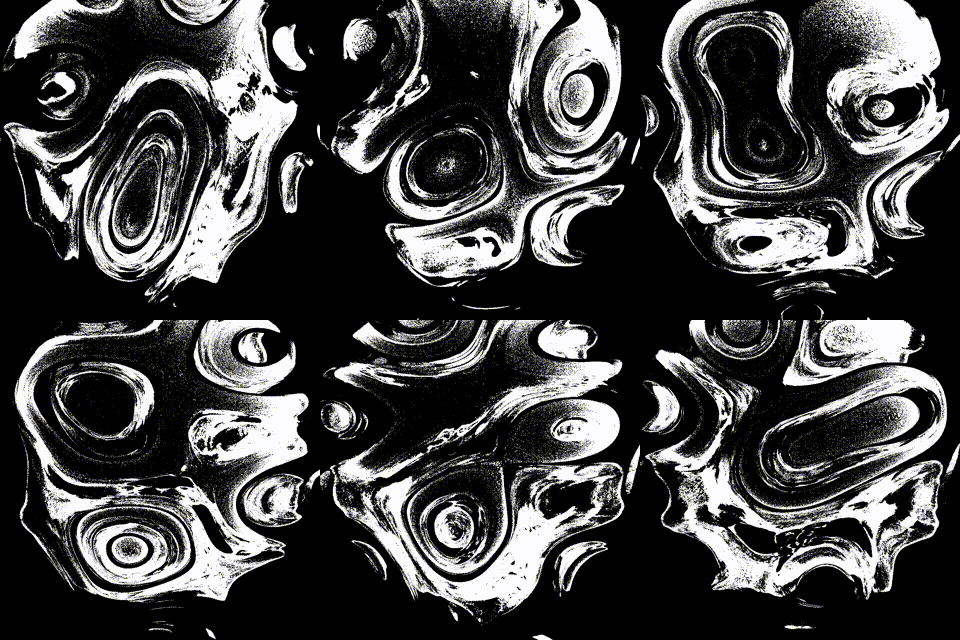
- offsetの値をNoise TOPで変更できるようにしているので,オフセットを変更するとスライスの深さが変更できる.
- Pythonを使用したスライスとは異なり,TOPの値を使用してスライスしているので,オフセットにもノイズをかけることができるようになった.

6. レイマーチングの実装
- フラグメントシェーダーでレイマーチングアルゴリズムを実装
#define MAX_MARCH_STEPS 256
uniform vec4 uDiffuseColor;
uniform vec4 uAmbientColor;
uniform vec3 uSpecularColor;
uniform float uShininess;
uniform float uShadowStrength;
uniform vec3 uShadowColor;
uniform mat4 mCamera; // 4x4 Camera matrix
uniform vec4 uCamera; // FOV, View angle method, near, far
uniform vec2 uRenderResolution; // Resolution of Render TOP
uniform sampler3D sColorMap;
// 回転行列ã®uniform変数を追åŠ
uniform mat4 uRotationMatrix;
in Vertex {
vec4 color;
vec3 worldSpacePos;
vec3 worldSpaceNorm;
vec3 texCoord0;
flat int cameraIndex;
}vVert;
// Output variable for the color
layout(location = 0) out vec4 fragColor[TD_NUM_COLOR_BUFFERS];
// Data structure to represent a ray
struct Ray
{
vec3 origin;
vec3 direction;
};
// Calculates the ray origin and direction based on the uv coordinate, the camera matrix and parameters.
Ray UVToRay(vec2 uv)
{
vec2 res = uRenderResolution.xy; // Render resolution in pixels
// Calculates the right angle based on the 'fov' and 'viewing angle method' of the camera.
float z = mix(res.x, res.y, uCamera.y) / tan(radians(uCamera.x) * 0.5) * 0.5;
uv -= 0.5; // Center the coordinate (0,0) should be in the center of the screen.
return Ray(
mCamera[3].xyz, // Extract the camera position
mat3(mCamera) * normalize(vec3(uv * res, -z)) // Rotate the direction based on the matrix
);
}
// The raymarch loop. Steps through the scene until it hits an object. Returns the distance to that object.
float March(Ray ray, float maxDistance)
{
// Make sure we move forward.
float distanceStep = 0.05;
float distanceOrigin = 0.0;
float energy = 0.0;
for (int i = 0; i < MAX_MARCH_STEPS; i++) {
distanceOrigin += distanceStep;
// Find the new position in space.
vec3 p = ray.origin + ray.direction * distanceOrigin;
vec4 rotatedPos = uRotationMatrix * vec4(p, 1.0);
vec3 samplingPos = rotatedPos.xyz + 0.5; // [0, 1]空間ã«å¤‰æ›
vec4 colorMapColor = texture(sColorMap, samplingPos);
float threshold = 0.5;
if (colorMapColor.r > threshold) {
// return distanceOrigin;
energy += colorMapColor.r/threshold;
}
}
return energy;
}
// out vec4 fragColor;
void main()
{
// vec2 uv = vUV.st;
vec3 texCoord0 = vVert.texCoord0.stp;
vec2 uv = texCoord0.st;
Ray ray = UVToRay(uv); // Calculate the ray based on the uv coordinate.
float dist = March(ray, uCamera.w); // Raymarches the scene and returns the distances to the closest surface of any object.
vec4 color = vec4(vec3(dist), 1.0);
fragColor[0] = TDOutputSwizzle(color);
// fragColor[0] = TDOutputSwizzle(vec4(uCamera.xyz, 1.0));
// TD_NUM_COLOR_BUFFERS will be set to the number of color buffers
// active in the render. By default we want to output zero to every
// buffer except the first one.
for (int i = 1; i < TD_NUM_COLOR_BUFFERS; i++)
{
fragColor[i] = vec4(0.0);
}
}
- カメラの位置と方向を考慮してレイの方向を計算
- ここでは,カメラの位置とオブジェクトの変更を考慮するために,mCamera, uCamera, uRotationMatorixという変数を渡して処理している.

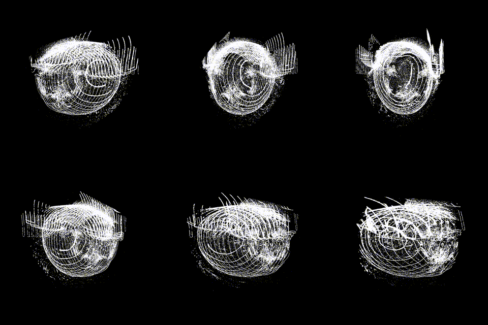
以上がうまくいくと以下のようなボリュームレンダリングが可能です.

Discussion