Building a Compact STM32 Robotic Arm for Automated Material Handling
Introduction
Automation has become the heartbeat of modern manufacturing. With the global push toward Industry 4.0, companies are continuously seeking ways to reduce repetitive labor, minimize human error, and boost production efficiency. Among the countless innovations driving this shift, robotic arms have taken a leading role. They combine mechanical precision with digital intelligence, enabling a wide range of industrial tasks once handled exclusively by human operators.
Today’s material-handling systems rely heavily on robotic manipulators to perform actions such as picking, sorting, packaging, and assembly. Compared to traditional manual workflows, these systems deliver faster response, higher accuracy, and greater consistency. In particular, compact robotic arms are gaining attention for small-scale or modular applications—where agility, cost efficiency, and space optimization are vital.
This article explores the design and development of a six-degree-of-freedom robotic arm powered by an STM32 microcontroller, emphasizing its compact architecture, control algorithms, and communication interface. The design reflects a balance between mechanical simplicity and system-level versatility—offering a practical model for educational, research, and light industrial projects.
For those interested in a more detailed exploration of embedded robotic control, check out this excellent resource on STM32-based robotic arm design
Concept and System Overview
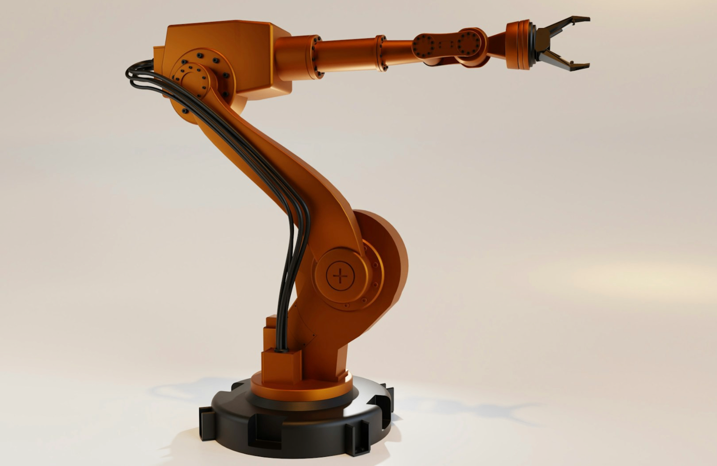
At its core, a robotic arm mimics the structure of a human limb: it consists of joints, links, and an end-effector. These elements work together to achieve controlled movement in three-dimensional space. The overall design can be divided into four primary modules:
- Mechanical structure – including the base, links, and gripper.
- Drive system – composed of six servo motors providing angular motion.
- Control electronics – an STM32F407-based controller generating PWM signals.
- User interface – an Android platform for wireless communication and remote operation.
Each joint is actuated by a servo motor capable of precise position control through a PWM signal generated by the MCU. The modular hardware layout makes debugging and firmware upgrades straightforward. This architecture also provides scalability—additional sensors or actuators can be integrated without major redesign.
Hardware Design
1. Controller Selection
The STM32F407ZET6 microcontroller sits at the center of the system. Featuring a 32-bit ARM Cortex-M4 core, it offers high-performance floating-point computation, multiple PWM channels, and rich I/O connectivity. These specifications make it ideal for controlling six servos simultaneously while maintaining real-time feedback.
Key hardware resources used:
- 192 KB SRAM and 1 MB Flash memory
- 12 × 16-bit general-purpose timers
- 2 × 32-bit timers
- 7 × PWM output channels
- 6 × UART/USART serial ports
This configuration supports multi-axis coordination and precise signal timing for smooth servo operation.
2. Servo Actuation
The robotic arm incorporates six servo motors divided into two groups:
- YF-6125MG (torque: 25 kg·cm, continuous 360° rotation) – used for the base and mid-arm joints.
- MG996R (torque: 13 kg·cm, limited 0–180° rotation) – applied to the wrist and gripper sections.
Servos interpret PWM pulses from the MCU:
- 1.5 ms pulse → neutral position
- 2.0 ms pulse → clockwise rotation
- 1.0 ms pulse → counter-clockwise rotation
By varying the pulse width within this range, the controller defines each joint’s angular displacement with high accuracy. The servos’ internal feedback potentiometers ensure closed-loop positioning, resulting in stable motion even under load.
3. Mechanical Configuration
The mechanical structure adopts a linkage-based design that enables complex motion paths while maintaining compactness. Each linkage joint contributes one degree of freedom, culminating in six axes of rotation: base yaw, shoulder pitch, elbow pitch, wrist roll, wrist pitch, and gripper motion.
The lightweight aluminum alloy frame provides a balance between rigidity and ease of assembly. To minimize backlash, precision ball bearings and rigid couplers are used at critical pivot points. The modular build allows the arm to be mounted on different bases or integrated into larger automation cells.
System Control Architecture
The robotic arm follows a distributed control logic. Commands flow from the Android interface through a wireless channel to the STM32 board, which interprets them into PWM signals for the servo drivers. The overall control process is summarized as follows:
- Android app sends movement parameters (angles, positions, grip command).
- Data is received via Wi-Fi module and parsed by the STM32 controller.
- MCU generates six synchronized PWM outputs.
- Servos execute the motion and provide position feedback.
- Sensor modules detect position completion or obstacles.
The control flow ensures real-time feedback and synchronized actuation across all axes. Because each servo operates independently, any joint can be recalibrated or replaced without affecting the rest of the system.
Software Implementation
1. Firmware Development
Firmware is developed using Keil µVision, a widely adopted IDE for ARM-based MCUs. The firmware is written in C, following a modular structure with independent drivers for:
- Servo PWM generation
- Serial communication
- Sensor data acquisition
- System timing and interrupts
During initialization, all global variables are set, the system clock is configured, and interrupt routines are enabled. Once the system enters the main loop, the MCU continuously listens for motion commands and executes corresponding servo actions.
To maintain stable motion, the program incorporates PID-based angle correction. The proportional and integral coefficients are tuned experimentally to achieve smooth trajectories without overshoot.
2. Android Interface
The Android control application—developed in Android Studio—serves as the human-machine interface. It allows operators to:
- Input target coordinates or joint angles
- Monitor the current arm posture in real time
- Trigger gripping, lifting, and releasing actions
Communication between the Android app and STM32 occurs through a Wi-Fi module (ESP8266). The MCU uploads telemetry data, while the app sends command packets formatted in JSON. This lightweight protocol keeps latency low and enhances cross-platform compatibility.
Calibration and Posture Control
After assembly, mechanical imperfections often lead to slight misalignments. To address this, the system includes a calibration procedure:
- Move the arm to a defined zero pose (reference position).
- Measure each joint’s offset angle.
- Save the offsets to non-volatile memory.
- Apply corrections automatically during each power-up.
This ensures accurate kinematics even after long-term use or mechanical wear. For applications requiring higher precision, the same calibration logic can be extended using external sensors such as encoders or IMUs.
Handling and Motion Execution
In a basic operation cycle:
- The Android app sends a “transfer” command.
- The arm moves to the pick-up location.
- Infrared sensors confirm object presence.
- The gripper closes, lifts the item, and moves it to the target point.
- The gripper opens, and the arm returns to the home position.
This simple pick-and-place sequence demonstrates how even a low-cost embedded controller can achieve repeatable multi-axis coordination when properly tuned.
For heavier or more dynamic loads, the firmware can be extended with acceleration profiles or spline interpolation to smooth motion transitions between waypoints.
System Testing and Validation
Bench testing focused on verifying servo synchronization, motion repeatability, and wireless reliability. The STM32 firmware was iteratively debugged via serial logging, and the arm’s real-time feedback confirmed millisecond-level command responsiveness.
The prototype achieved:
- Positional repeatability: ±1.2° per joint
- Communication delay: < 40 ms
- Continuous runtime: 8 hours without overheating
Such performance indicates that the STM32 controller and modular structure are adequate for light industrial and educational use cases.
Future Enhancements
While the current implementation meets essential automation needs, future iterations could benefit from:
- Force and torque sensors for adaptive gripping
- Computer vision modules for object detection
- AI-assisted trajectory planning for optimized motion paths
- CAN bus integration to replace Wi-Fi for deterministic control
These upgrades would elevate the system from a basic manipulator to a smart collaborative robot (cobot) capable of dynamic, context-aware interaction.
Conclusion
This project demonstrates a compact, affordable, and extensible robotic arm built on the STM32 platform. By leveraging open-source development tools and modular design, it achieves precise motion control without relying on costly industrial components.
The combination of embedded hardware, servo-driven actuation, and Android-based control creates a versatile platform for laboratories, makers, and automation startups seeking to prototype material-handling solutions.
By focusing on simplicity, openness, and efficiency, this STM32 robotic arm shows how modern embedded systems continue to bridge the gap between industrial automation and accessible innovation.
Discussion