React+TypeScriptでWebAssembly009。純粋C++。OpenCV,QRコードの検出を実装してみた。
<- React+TypeScriptでWebAssembly008
React+TypeScriptでWebAssembly010 ->
Abstract
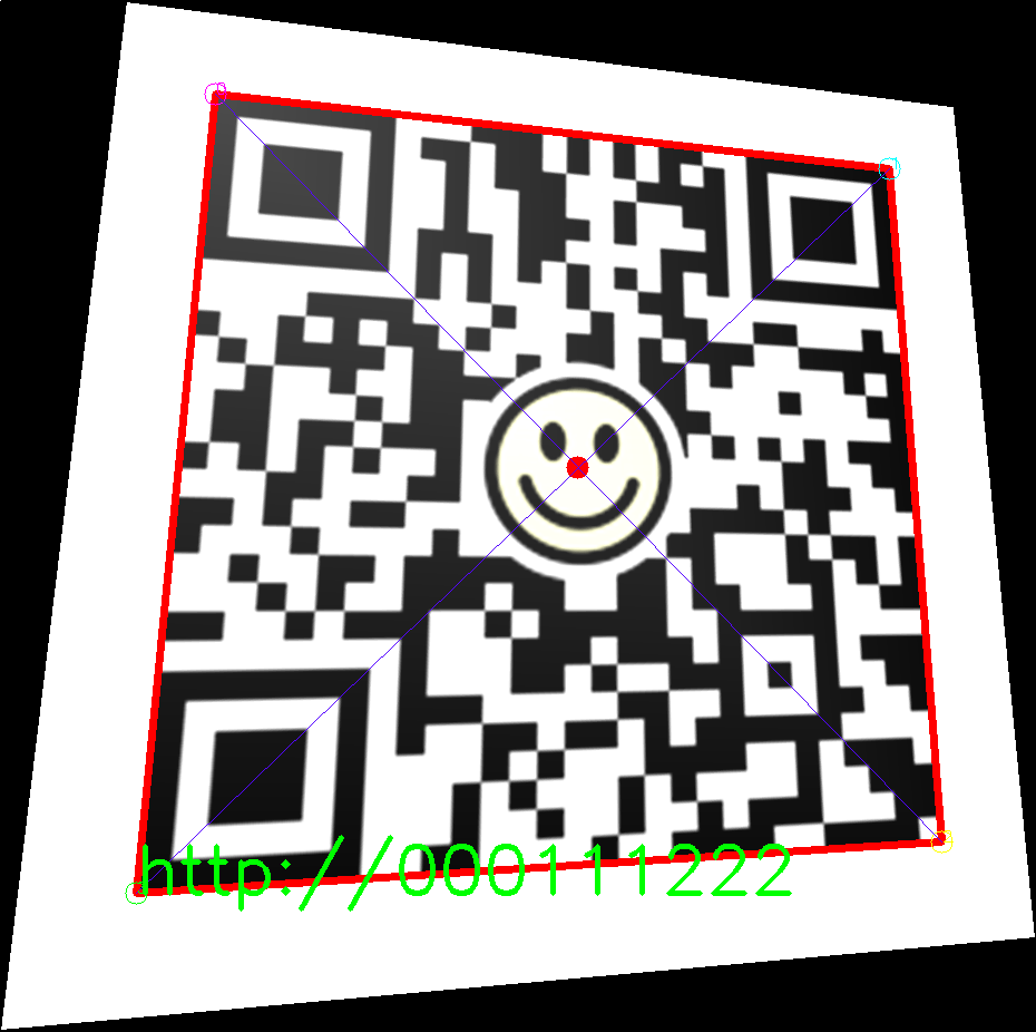
OpenCV,C++でQRコード読み込みのコードを実装してみた。
最終的にはWebAssemblyにするものの、ひとまず純粋C++アプリで。
結論
今回の成果物はココ↓
前提
- windowsでOpenCV,C++の開発環境構築済み。 [環境構築]React+TypeScriptでWebAssembly002。WindowsでOpenCV,C++,VSCode,CMake。
- WebAssemblyのビルド環境も構築済み。[環境構築]Ubuntu22.04で、WebAssemblyのOpenCV,C++,CMakeの開発環境を構築してみた。
- React+Typescriptの開発環境は構築済 [環境構築]WindowsにVSCode+React+TypeScriptの開発環境を構築してみた。
- ベースはこれ→reacttscppwasm_tmplate。
WindowsでC++開発。
準備
1.テンプレートのソースコード一式を取得
$ cd D:\Products\React.js
$ git clone https://github.com/aaaa1597/reacttscppwasm_tmplate.git
$ ren reacttscppwasm_tmplate ReactTs-WebAsm009
$ cd ReactTs-WebAsm009/cpp
2. VSCodeでプロジェクトフォルダを開く
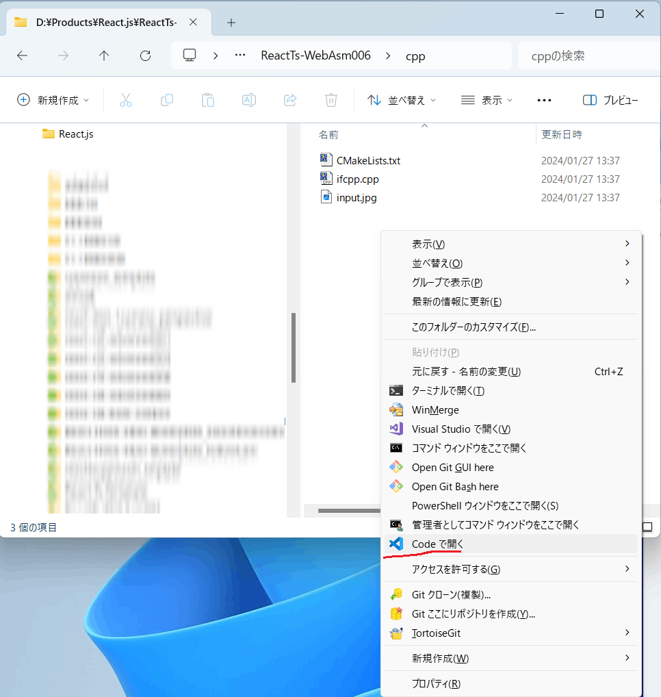
VSCodeの拡張機能C/C++、CMake Toolsを入れてなければ入れておく。
↓
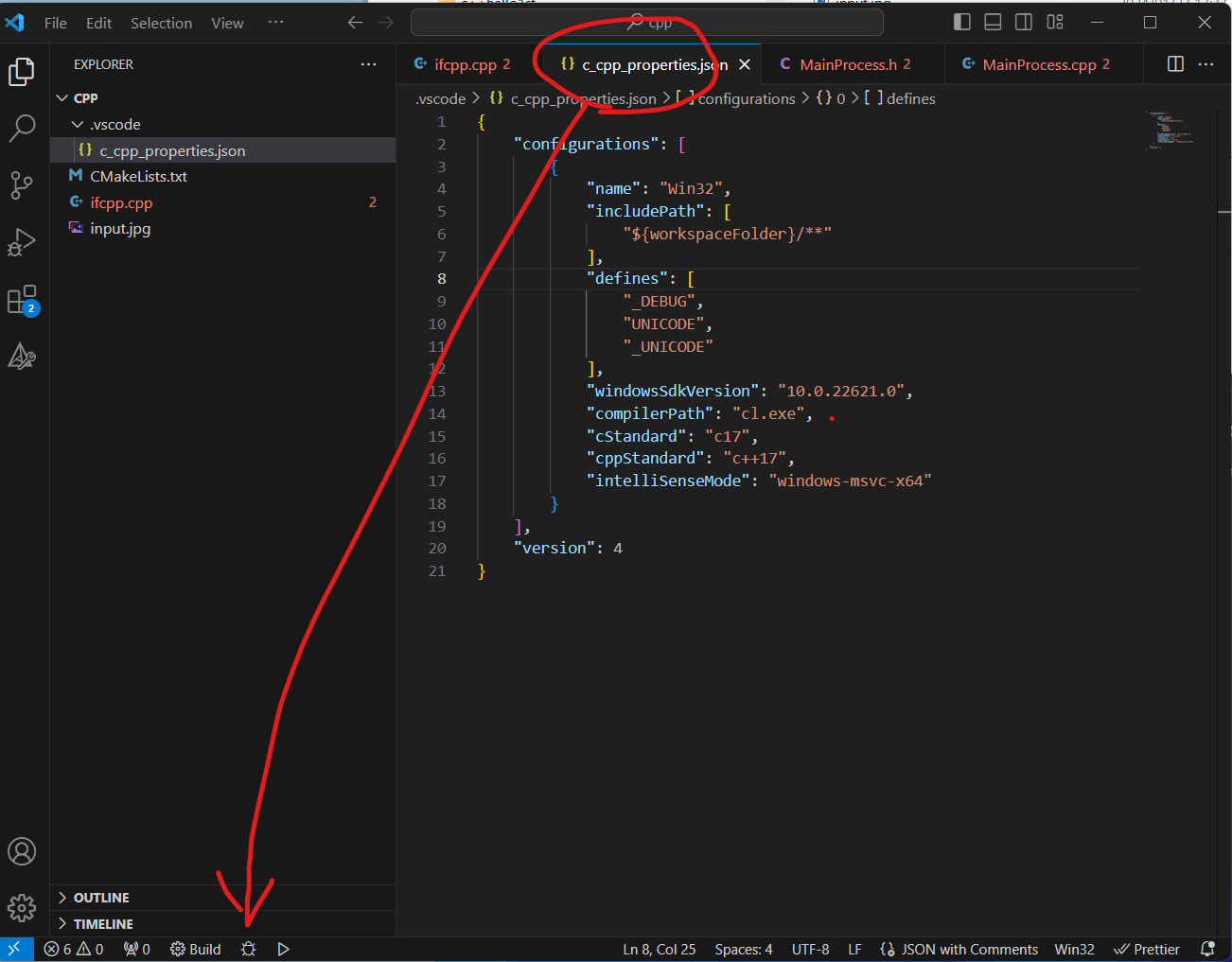
- C/C++: Edit Configurations(JSON)を選択
Ctrl + Shift + P -> "C/C++: Edi"まで入力と出てくる。

↓
c_cpp_properties.jsonが生成される。ついでに右下にビルド/デバッグ/実行ボタンも表示される。
3. CMakeの設定
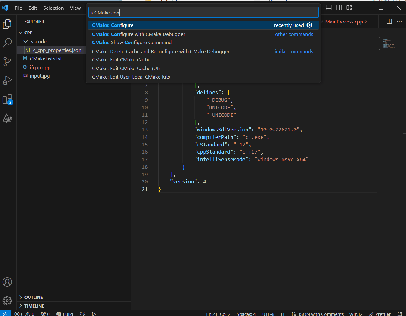
Ctrl + Shift + P -> "CMake: Configure"を選択。
X86を選ぶ。(WebAssemblyは32bitなので。)
↓

4. インクルードパスを追加
ifcpp.cppに戻ると、赤波線でエラーになっている。

↓
OpenCVのインストールパスを設定。
D:\apps\opencv\opencv-4.x\build\install\include

↓
赤波線が消えている。

5. 実行
ブレークポイントを設定して、カブト虫ボタンを押す。

↓
ちょっと待つと、ブレークポイントで止まる。

↓
再開

準備完了。
ここからQRコード読み込み処理を実装する。
OpenCV,QRコード読み込みの実装
手順
1. QRコード準備
QRコードの準備。以下のQRコードを使う。
正解文字列 : "http://000111222"

2. QRコード読込み
準備したQRコードを読込む。今回は動かすのが目的だから、ファイルを直接読込んでいる。先々カメラから読み込むように変更する予定。
 9:  std::string file = "../../QR_sample6.png";
10:  /* 画像の読み込み */
11:  cv::Mat inputImage = cv::imread(file);
12:  cv::Mat outputImage;
13:  inputImage.copyTo(outputImage);
11行目で直接読み込んでいる。
13行目で、検出結果をいろいろ書き込むための出力用イメージを作成している。
3. 計測開始/終了
24:    std::chrono::steady_clock::time_point stime = std::chrono::steady_clock::now();
~略~
62: /* 計測終了 */
63:  std::chrono::steady_clock::time_point etime = std::chrono::steady_clock::now();
64:  long elapsedtime = std::chrono::duration_cast<std::chrono::milliseconds>(etime - stime).count() % 1000;
65:  std::cout << "elapsedtime: " << elapsedtime << "ms." << std::endl;
QRコードとは関係ないけど、モダンなC++は時間操作に、std::chronoを使う。
4. 出力引数定義
26:  std::vector<std::string> decoded_info;
27:  std::vector<cv::Point> points;
28://  std::vector<cv::Mat> straight_codes;  /* 第4引数はQRコードのビットパターンが設定される */
cv::QRCodeDetector::detectAndDecodeMulti()を呼び出し後に結果が格納される出力引数を定義。
コメントに記述の通りなんだけど、第4引数は検出したQRコードのビットパターンが設定される。
使い道は分かんない。デバッグ用かな?
5. 検出とデコード
31: qrcode_detector.detectAndDecodeMulti(inputImage, decoded_info, points/*,straight_codes*/);
検出とデコード。そのまんま。
6. 結果をいろいろ描画
36:  for(size_t lpct = 0; lpct < decoded_info.size(); lpct++) {
37:    /* 枠線描画 */
38:    cv::line(outputImage, cv::Point(points[lpct*4+0].x, points[lpct*4+0].y), cv::Point(points[lpct*4+1].x, points[lpct*4+1].y), cv::Scalar(0,0,255), 5);
39:    cv::line(outputImage, cv::Point(points[lpct*4+1].x, points[lpct*4+1].y), cv::Point(points[lpct*4+2].x, points[lpct*4+2].y), cv::Scalar(0,0,255), 5);
40:    cv::line(outputImage, cv::Point(points[lpct*4+2].x, points[lpct*4+2].y), cv::Point(points[lpct*4+3].x, points[lpct*4+3].y), cv::Scalar(0,0,255), 5);
41:    cv::line(outputImage, cv::Point(points[lpct*4+3].x, points[lpct*4+3].y), cv::Point(points[lpct*4+0].x, points[lpct*4+0].y), cv::Scalar(0,0,255), 5);
42:    /* 頂点描画 */
43:    cv::circle(outputImage, cv::Point(points[lpct*4+0].x, points[lpct*4+0].y), 10, cv::Scalar(255,   0, 255));
44:    cv::circle(outputImage, cv::Point(points[lpct*4+1].x, points[lpct*4+1].y), 10, cv::Scalar(255, 255,   0));
45:    cv::circle(outputImage, cv::Point(points[lpct*4+2].x, points[lpct*4+2].y), 10, cv::Scalar(  0, 255, 255));
46:    cv::circle(outputImage, cv::Point(points[lpct*4+3].x, points[lpct*4+3].y), 10, cv::Scalar(  0, 255,   0));
47:    /* 交点描画 */
48:    cv::Point center = CrossLineLine(points[lpct*4+0], points[lpct*4+1], points[lpct*4+2], points[lpct*4+3]);
49:    cv::circle(outputImage, center, 10, cv::Scalar( 0, 0,255), -1);
50:    /* 交点補助線描画 */
51:    cv::line(outputImage, cv::Point(points[lpct*4+0].x, points[lpct*4+0].y), cv::Point(points[lpct*4+2].x, points[lpct*4+2].y), cv::Scalar(255,7,85));
52:    cv::line(outputImage, cv::Point(points[lpct*4+1].x, points[lpct*4+1].y), cv::Point(points[lpct*4+3].x, points[lpct*4+3].y), cv::Scalar(255,7,85));
53:    /* 頂点番号描画 */
54:    cv::putText(outputImage, "0", cv::Point(points[lpct*4+0].x, points[lpct*4+0].y), cv::FONT_HERSHEY_SIMPLEX, 0.5, cv::Scalar(255,   0, 255));
55:    cv::putText(outputImage, "1", cv::Point(points[lpct*4+1].x, points[lpct*4+1].y), cv::FONT_HERSHEY_SIMPLEX, 0.5, cv::Scalar(255, 255,   0));
56:    cv::putText(outputImage, "2", cv::Point(points[lpct*4+2].x, points[lpct*4+2].y), cv::FONT_HERSHEY_SIMPLEX, 0.5, cv::Scalar(  0, 255, 255));
57:    cv::putText(outputImage, "3", cv::Point(points[lpct*4+3].x, points[lpct*4+3].y), cv::FONT_HERSHEY_SIMPLEX, 0.5, cv::Scalar(  0, 255,   0));
58:    /* URL文字列描画 */
59:    cv::putText(outputImage, decoded_info[lpct], cv::Point(points[lpct*4+3].x, points[lpct*4+3].y), cv::FONT_HERSHEY_SIMPLEX, 2, cv::Scalar(  0, 255,   0), 3, 8, false);
60:  }
コメントの通りだけど、48行目で2線分の交点を算出している。頭いい人たちには簡単な数学らしいけどムズかったポイント。
7. 出力画像を保存
74: cv::imwrite(outfile, outputImage);
結果画像出力。
で、実行。

出来た!!
elapsedtime: 641ms.
処理時間がだいぶかかっているのが課題だけど、一応出来た。
- デバッグ時のお助け情報1
Matの中身ってそのままだと確認しづらいけど、下記方法で確認しやすくなる。
https://qiita.com/h2suzuki/items/6b40f69bb287799d8bf6
<- React+TypeScriptでWebAssembly008
React+TypeScriptでWebAssembly010 ->
Discussion