スイッチサイエンス製BLE Pro MicroボードをRaspberry Pi Picoでデバッグ/flashする
↑のSWDデバッグを↓でやるメモ。
SWD
ArmのCortexシリーズにはSWD(Serial Wire Debug)機能があり、JTAG相当のデバッグ機能を2本 + GNDの計3本のケーブルで実現できる。 ...これシングルワイヤデバッグだと思ってて全然シングルじゃないじゃん!とわざわざ調べてしまった。。
SWDを使うと:
- CPU上で動作するアプリケーションを通常のPC上のアプリケーションのようにデバッグできる。例えば実行を止めたりブレークポイントを貼ったりといった作業がOS側のサポートなしで行える。
- 例外等でCPUが停止したときにデバッガに通知が飛ぶ。
- ターゲット側のbootloaderを使用しなくても内蔵Flashを操作できる。
どう考えても開発に必須で無いと困る。いやまぁUARTデバッグなりLEDデバッグでも良いけど。。
Picoprobeの準備
Raspberry Pi PicoをSWDインターフェースとして利用するためのpicoprobeが開発元から公開されている。
これはドキュメント https://datasheets.raspberrypi.com/pico/getting-started-with-pico.pdf Appendix A の通り本来はRasipberry Pi Pico同士で使うことを想定しているものだが、別に3.3v系のArmプロセサでSWDをサポートしているものであれば何にでも使える。
PicoのPicoprobe化
公式サイト https://www.raspberrypi.com/documentation/microcontrollers/raspberry-pi-pico.html#debugging-using-another-raspberry-pi-pico からUF2ファイルをDLし、RaspberryPi Picoに書き込む。
-
BOOTSELを押しながらUSBを接続する - マスストレージデバイスとしてマウントされるのでダウンロードしたUF2をコピー
- 自動的に再起動してPicoprobeとして動作しはじめる
Windows用のドライバを導入する
Windows上ではPicoprobeのドライバは用意されていないので、Zadigで適当にlibusbをインストールする。
手順は Getting Started with Raspberry Pi Pico の Install Picoprobe driver 節で説明されている。
結線
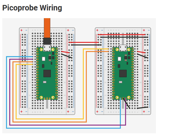
ドキュメントにはPico同士での結線が乗っている。

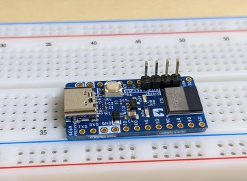
PicoのUSBコネクタの反対側には DEBUG として3ピンの端子があるが、これをMicroボードのSWDピンに接続することになる。MicroボードにはPicoの3ピンに加えてVccの計4ピンがある。この4ピンが、通常のPro Microのピン より内側の 4ピン として基板に設けられているので、そこにピンヘッダなりなんなりを接続する。

USBコネクタ側から順番に GND SWCLK SWIO Vcc となっているので、 Vcc 以外をPicoの対応するピンに接続する。
OpenOCD(GDB stub)の準備
Picoprobeは本家OpenOCDはサポートしていないので、Raspberry Pi側のforkである https://github.com/raspberrypi/openocd をビルドする。このforkはちょっと古いが、今回デバッグしたいMicroボードに搭載されているチップはRaspberry Pi Picoより更に古いので特に問題はない。
Cygwinでビルドするとエラーになる
src/flash/nor/rp2040.c:150: error: "PAGE_SIZE" redefined [-Werror]
  150 | #define PAGE_SIZE 256
      |
In file included from /usr/lib/gcc/x86_64-pc-cygwin/11/include/limits.h:203,
                 from /usr/lib/gcc/x86_64-pc-cygwin/11/include/syslimits.h:7,
                 from /usr/lib/gcc/x86_64-pc-cygwin/11/include/limits.h:34,
                 from /usr/include/sys/param.h:12,
                 from ./src/helper/system.h:67,
                 from ./config.h:358,
                 from src/flash/nor/rp2040.c:2:
/usr/include/limits.h:222: note: this is the location of the previous definition
  222 | #define PAGE_SIZE PAGESIZE
      |
これはCygwinの <sys/param.h> が <limits.h> をpull-inしているために起こる。この問題はFreeBSDにもあるようで、pull requestが出ている。
デバッグ
MicroボードにはBluetooth搭載のArmチップとしてISP1805が搭載されていて、これはNordicの nRF52 を内蔵している。OpenOCDは target/nrf52.cfg としてスクリプトを同梱しているので、それをそのまま利用できる。
OSなしデバッグ
-
openocd -f interface/picoprobe.cfg -f target/nrf52.cfgとして OpenOCDを起動する - gdb側から
target extended-remote localhost:3333としてOpenOCDに接続する
接続に成功すると、CPUが停止して通常のプログラムのブレークと同様に表示される。
(gdb) target extended-remote localhost:3333
Remote debugging using localhost:3333
0x00028a66 in HardFault_Handler ()
(gdb) bt
#0  0x00028a66 in HardFault_Handler ()
#1  <signal handler called>
#2  _start ()
    at /cygdrive/f/armnone-m4f/crosstool-ng/.build/arm-none-eabihf/src/newlib/newlib/libc/sys/arm/crt0.S:275
#3  0x00028a4e in Reset_Handler ()
Backtrace stopped: previous frame identical to this frame (corrupt stack?)
(gdb)
OpenOCDをgdbから操作するには monitor コマンドを使用する。例えば、 monitor reset でターゲットをリセットできる。
OS有りデバッグ
Microボードで使用しているArduino Core(Adafruit製)はFreeRTOSをOSとして採用している。OpenOCDはこの手のRTOSのサポートが内蔵されていて、それを利用するとRTOS上のスレッドをGDB内で切り替えながらデバッグできる。
OpenOCDが必要な変数がArduino Core側のFreeRTOSから消されてしまっているので、事前に復活させる必要がある。
openocd -f interface/picoprobe.cfg -f target/nrf52.cfg -c "\$_TARGETNAME configure -rtos auto" としてOpenOCDを起動し、スクリプトで rtos を設定すると、GDBの接続時に自動的にOSが認識され、 info threads 等でスレッドが参照できるようになる。
(gdb) info threads
  Id   Target Id                                     Frame
  1    Thread 536903924 (Name: IDLE, State: Running) vPortSuppressTicksAndSleep (xExpectedIdleTime=512)
    at ../Adafruit_nRF52_Arduino/cores/nRF5/freertos/portable/CMSIS/nrf52/port_cmsis_systick.c:213
  2    Thread 536909720 (Name: loop)                 __ISB () at ../CMSIS_5/CMSIS/Core/Include/cmsis_gcc.h:935
  3    Thread 536914128 (Name: usbd)                 __ISB () at ../CMSIS_5/CMSIS/Core/Include/cmsis_gcc.h:935
* 4    Thread 536913232 (Name: Callbac)              __ISB () at ../CMSIS_5/CMSIS/Core/Include/cmsis_gcc.h:935
  5    Thread 536904408 (Name: Tmr Svc)              __DSB () at ../CMSIS_5/CMSIS/Core/Include/cmsis_gcc.h:946
フラッシュ書き込み
フラッシュの操作はOpenOCD側のtelnet(ポート 4444 )に接続して行う。
Open On-Chip Debugger
> flash banks
#0 : nrf52.flash (nrf5) at 0x00000000, size 0x00100000, buswidth 1, chipwidth 1
#1 : nrf52.uicr (nrf5) at 0x10001000, size 0x00001000, buswidth 1, chipwidth 1

> flash read_bank 0 flash-bank0.bin
wrote 1048576 bytes to file flash-bank0.bin from flash bank 0 at offset 0x00000000 in 64.920067s (15.773 KiB/s)


> flash write_image erase e1ca004f-0f23-49d9-b7b9-51745d35fd77.hex 0 ihex
nRF52840-CKAA(build code: D0) 1024kB Flash, 256kB RAM
Padding image section 0 at 0x00000b00 with 1280 bytes
Flash write discontinued at 0x00025de8, next section at 0x000f4000
Adding extra erase range, 0x00025de8 .. 0x00025fff
Padding image section 2 at 0x000fc110 with 5872 bytes
Adding extra erase range, 0x000fd858 .. 0x000fdfff
Adding extra erase range, 0x10001000 .. 0x10001013
Adding extra erase range, 0x1000101c .. 0x10001fff
auto erase enabled
wrote 194120 bytes from file e1ca004f-0f23-49d9-b7b9-51745d35fd77.hex in 19.191427s (9.878 KiB/s)