#M5Stack ATOM LiteでFire TVのバグを「「修正」」する
本記事はM5Stack Advent Calendar 2023の7日目の記事です
Fire TV Stickシリーズ 長年のバグ
余ったPCモニターへFire TV Stickを挿してアマプラ端末化する際にどうしても許せないのがFire TVをスリープさせたときの挙動です
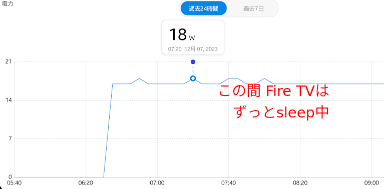
Fire TV本体をスリープさせてもHDMI信号出力がオフにならないため、モニターの省電力機能が効かず黒画面をずっと表示しっぱなしになります
これは有名な問題で、Amazon本家フォーラムでも2019年に立ったスレッドが未解決のまま放置されています
キューブ型のFire TVではスリープ時にHDMI信号がオフになるようですがStickシリーズはずっと(おそらく2014年版の最初のFire TV Stickから)ダメです
PCモニターをこの状態で放置すると案外電力を消費します
手元のLG 4Kモニターは映像音声出力をすると18-20Wの間を行き来しますが、ただ黒画面を表示し続けるだけでも17-18W消費しており、映像音声出力時と大差ないことがわかります
仮に100万台のFire TVに接続されたPCモニターが同様の電力を浪費していたら、その浪費は年間109GWhに及ぶ計算です(稼働率30%として試算)
残念ながらAmazonのサステナビリティレポートにFire TVの省電力性能への言及はありませんが、公式がやらないならば自分たちでなんとかしましょう
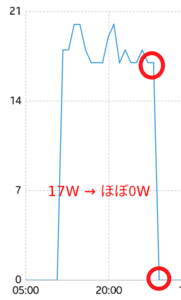
これぐらい変わります
システム構成要素
自分の利用スタイルにあわせてシステムの構成要素を検討していきます
電源操作手段に音声コマンドを採用するか否か、という設計上の大きな分かれ道がありますが
そもそも私はFire TVを常にリモコンで操作するため、リモコンを手に持ちつつ電源操作に別途発声を必要とするのはちぐはぐで実用時にストレスが溜まると想定できました
このため、Fire TVリモコンの1ボタンで操作できることを必須条件とします
電源ボタンを押して1秒程度、音声コマンドより圧倒的に速くモニターの電源が入る/落ちるレスポンス感を目標として、次に挙げる要素で構成することにしました
- Fire TV Stick 4K Max 第1世代
- Fire TVリモコン
- LG 4Kモニター
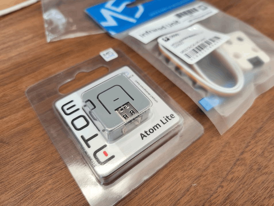
- ATOM Lite
- M5Stack用赤外線送受信ユニット U002
- Tapo P110M
- 適当なPC/ラズパイ的なもの(PythonのプロセスをホストできればなんでもOK)
Fire TVリモコンが2.4GHz帯の電波に加えて赤外線も噴いていることを利用し、本来テレビの代替リモコンとして機能するように出している信号をATOM Liteで拾ってWi-Fiで宅内のPCへ転送→スマートプラグを制御してモニターの電源をOn/Offする、という構造です
Fire TVリモコンの電源ボタン押下を検出する
機能を実現するために、まずはFireTVのリモコンが出力している赤外線パターンを調べます
弊宅のFire TVはLGのモニターへ接続しており、Fire TV側でその旨を軽く設定してあるためLG向けの信号が出ます
このあたりは接続するモニターによって試行錯誤が必要です
生の赤外線パターン自体は毎回変わるのでビットパターンとしてハードコードするのは無理です
このエリアでよく使われるライブラリであるIRremoteESP8266のサンプルコードは非常に便利な作りになっており、実行するとひたすら赤外線信号を検出して機能実装に便利な参考情報としてダンプしてくれます
Library   : v2.8.6

Protocol  : NEC
Code      : 0x20DF10EF (32 Bits)
uint16_t rawData[67] = {8970, 4430,  532, 494,  556, 494,  556, 1672,  536, 492,  556, 494,  556, 494,  556, 494,  558, 492,  558, 1672,  536, 1670,  536, 492,  556, 1674,  532, 1672,  534, 1672,  534, 1672,  534, 1674,  534, 494,  556, 516,  532, 494,  558, 1672,  532, 494,  556, 516,  534, 516,  534, 516,  536, 1672,  532, 1674,  534, 1672,  532, 520,  532, 1672,  536, 1672,  532, 1674,  534, 1672,  532};  // NEC 20DF10EF
uint32_t address = 0x4;
uint32_t command = 0x8;
uint64_t data = 0x20DF10EF;
これにより、
- 信号タイプはNEC
- addressは4
- commandは8
が流れてくることがわかります
実際のコードはESP-IDFベースで書いても良いのですが、今回は最低限HTTPっぽいパケットを投げられれば事足りるのでサンプルスケッチの変形程度でさっと動くArduino構成を選択しました
コア部分は次のとおりです
    if (results.decode_type == NEC && results.address == 4 && results.command == 8) {
      Serial.println("Power button pressed.");
      WiFiClient client;
      if (client.connect("192.168.0.157", 4080)) {
        client.print("GET /toggleTvPower HTTP/1.1\r\nHost: 192.168.0.157\r\nConnection: close\r\n\r\n");
        delay(500);
        client.stop();
      }
    }
リモコンの赤外線出力はスイッチを押し続けると(押し続けなくても)コマンドをリピートするケースが多く、そのうち1回だけを抽出したい・またTCPパケットが確実に届いてから接続を切りたかったので500msのディレイを入れています
うまく動作していますね
ボタンを押してからPC上で動作しているPythonプロセスでパケット内容を出力するところまでほとんどタイムラグがないことがわかります
setupとloopの全文は次のとおりです
元コードを #if 0 で潰してWi-Fi経由のパケット送信コードを追加したのみです
/*
 * IRremoteESP8266: IRrecvDumpV2 - dump details of IR codes with IRrecv
 * An IR detector/demodulator must be connected to the input kRecvPin.
 *
 * Copyright 2009 Ken Shirriff, http://arcfn.com
 * Copyright 2017-2019 David Conran
 *
 * Example circuit diagram:
 *  https://github.com/crankyoldgit/IRremoteESP8266/wiki#ir-receiving
 *
 * Changes:
 *   Version 1.2 October, 2020
 *     - Enable easy setting of the decoding tolerance value.
 *   Version 1.0 October, 2019
 *     - Internationalisation (i18n) support.
 *     - Stop displaying the legacy raw timing info.
 *   Version 0.5 June, 2019
 *     - Move A/C description to IRac.cpp.
 *   Version 0.4 July, 2018
 *     - Minor improvements and more A/C unit support.
 *   Version 0.3 November, 2017
 *     - Support for A/C decoding for some protocols.
 *   Version 0.2 April, 2017
 *     - Decode from a copy of the data so we can start capturing faster thus
 *       reduce the likelihood of miscaptures.
 * Based on Ken Shirriff's IrsendDemo Version 0.1 July, 2009,
 */

#include <M5Atom.h>
#include <assert.h>
#include <IRrecv.h>
#include <IRremoteESP8266.h>
#include <IRac.h>
#include <IRtext.h>
#include <IRutils.h>
#include <WiFi.h>

// ==================== start of TUNEABLE PARAMETERS ====================
// An IR detector/demodulator is connected to GPIO pin 14
// e.g. D5 on a NodeMCU board.
// Note: GPIO 16 won't work on the ESP8266 as it does not have interrupts.
// Note: GPIO 14 won't work on the ESP32-C3 as it causes the board to reboot.
#ifdef ARDUINO_ESP32C3_DEV
const uint16_t kRecvPin = 10;  // 14 on a ESP32-C3 causes a boot loop.
#else  // ARDUINO_ESP32C3_DEV
const uint16_t kRecvPin = 32;
#endif  // ARDUINO_ESP32C3_DEV

// The Serial connection baud rate.
// i.e. Status message will be sent to the PC at this baud rate.
// Try to avoid slow speeds like 9600, as you will miss messages and
// cause other problems. 115200 (or faster) is recommended.
// NOTE: Make sure you set your Serial Monitor to the same speed.
const uint32_t kBaudRate = 115200;

// As this program is a special purpose capture/decoder, let us use a larger
// than normal buffer so we can handle Air Conditioner remote codes.
const uint16_t kCaptureBufferSize = 1024;

// kTimeout is the Nr. of milli-Seconds of no-more-data before we consider a
// message ended.
// This parameter is an interesting trade-off. The longer the timeout, the more
// complex a message it can capture. e.g. Some device protocols will send
// multiple message packets in quick succession, like Air Conditioner remotes.
// Air Coniditioner protocols often have a considerable gap (20-40+ms) between
// packets.
// The downside of a large timeout value is a lot of less complex protocols
// send multiple messages when the remote's button is held down. The gap between
// them is often also around 20+ms. This can result in the raw data be 2-3+
// times larger than needed as it has captured 2-3+ messages in a single
// capture. Setting a low timeout value can resolve this.
// So, choosing the best kTimeout value for your use particular case is
// quite nuanced. Good luck and happy hunting.
// NOTE: Don't exceed kMaxTimeoutMs. Typically 130ms.
#if DECODE_AC
// Some A/C units have gaps in their protocols of ~40ms. e.g. Kelvinator
// A value this large may swallow repeats of some protocols
const uint8_t kTimeout = 50;
#else   // DECODE_AC
// Suits most messages, while not swallowing many repeats.
const uint8_t kTimeout = 15;
#endif  // DECODE_AC
// Alternatives:
// const uint8_t kTimeout = 90;
// Suits messages with big gaps like XMP-1 & some aircon units, but can
// accidentally swallow repeated messages in the rawData[] output.
//
// const uint8_t kTimeout = kMaxTimeoutMs;
// This will set it to our currently allowed maximum.
// Values this high are problematic because it is roughly the typical boundary
// where most messages repeat.
// e.g. It will stop decoding a message and start sending it to serial at
//      precisely the time when the next message is likely to be transmitted,
//      and may miss it.

// Set the smallest sized "UNKNOWN" message packets we actually care about.
// This value helps reduce the false-positive detection rate of IR background
// noise as real messages. The chances of background IR noise getting detected
// as a message increases with the length of the kTimeout value. (See above)
// The downside of setting this message too large is you can miss some valid
// short messages for protocols that this library doesn't yet decode.
//
// Set higher if you get lots of random short UNKNOWN messages when nothing
// should be sending a message.
// Set lower if you are sure your setup is working, but it doesn't see messages
// from your device. (e.g. Other IR remotes work.)
// NOTE: Set this value very high to effectively turn off UNKNOWN detection.
const uint16_t kMinUnknownSize = 12;

// How much percentage lee way do we give to incoming signals in order to match
// it?
// e.g. +/- 25% (default) to an expected value of 500 would mean matching a
//      value between 375 & 625 inclusive.
// Note: Default is 25(%). Going to a value >= 50(%) will cause some protocols
//       to no longer match correctly. In normal situations you probably do not
//       need to adjust this value. Typically that's when the library detects
//       your remote's message some of the time, but not all of the time.
const uint8_t kTolerancePercentage = kTolerance;  // kTolerance is normally 25%

// Legacy (No longer supported!)
//
// Change to `true` if you miss/need the old "Raw Timing[]" display.
#define LEGACY_TIMING_INFO false
// ==================== end of TUNEABLE PARAMETERS ====================

// Use turn on the save buffer feature for more complete capture coverage.
IRrecv irrecv(kRecvPin, kCaptureBufferSize, kTimeout, true);
decode_results results;  // Somewhere to store the results

// This section of code runs only once at start-up.
void setup() {
  M5.begin(true, false, false);
  WiFi.begin("WI_FI_AP_NAME", "WI_FI_PSK");
  while (WiFi.status() != WL_CONNECTED) {
    delay(500);
    Serial.print(".");
  }
#if defined(ESP8266)
  Serial.begin(kBaudRate, SERIAL_8N1, SERIAL_TX_ONLY);
#else  // ESP8266
  Serial.begin(kBaudRate, SERIAL_8N1);
#endif  // ESP8266
  while (!Serial)  // Wait for the serial connection to be establised.
    delay(50);
  // Perform a low level sanity checks that the compiler performs bit field
  // packing as we expect and Endianness is as we expect.
  assert(irutils::lowLevelSanityCheck() == 0);

  Serial.printf("\n" D_STR_IRRECVDUMP_STARTUP "\n", kRecvPin);
#if DECODE_HASH
  // Ignore messages with less than minimum on or off pulses.
  irrecv.setUnknownThreshold(kMinUnknownSize);
#endif  // DECODE_HASH
  irrecv.setTolerance(kTolerancePercentage);  // Override the default tolerance.
  irrecv.enableIRIn();  // Start the receiver
}

// The repeating section of the code
void loop() {
  // Check if the IR code has been received.
  if (irrecv.decode(&results)) {
    // Display a crude timestamp.
    uint32_t now = millis();
    Serial.printf(D_STR_TIMESTAMP " : %06u.%03u\n", now / 1000, now % 1000);
    // Check if we got an IR message that was to big for our capture buffer.
#if 0
    if (results.overflow)
      Serial.printf(D_WARN_BUFFERFULL "\n", kCaptureBufferSize);
    // Display the library version the message was captured with.
    Serial.println(D_STR_LIBRARY "   : v" _IRREMOTEESP8266_VERSION_STR "\n");
    // Display the tolerance percentage if it has been change from the default.
    if (kTolerancePercentage != kTolerance)
      Serial.printf(D_STR_TOLERANCE " : %d%%\n", kTolerancePercentage);
    // Display the basic output of what we found.
    Serial.print(resultToHumanReadableBasic(&results));
    // Display any extra A/C info if we have it.
    String description = IRAcUtils::resultAcToString(&results);
    if (description.length()) Serial.println(D_STR_MESGDESC ": " + description);
    yield();  // Feed the WDT as the text output can take a while to print.
#endif
#if LEGACY_TIMING_INFO
    // Output legacy RAW timing info of the result.
    Serial.println(resultToTimingInfo(&results));
    yield();  // Feed the WDT (again)
#endif  // LEGACY_TIMING_INFO
#if 0
    // Output the results as source code
    Serial.println(resultToSourceCode(&results));
#endif
    if (results.decode_type == NEC && results.address == 4 && results.command == 8) {
      Serial.println("Power button pressed.");
      WiFiClient client;
      if (client.connect("192.168.0.157", 4080)) {
        client.print("GET /toggleTvPower HTTP/1.1\r\nHost: 192.168.0.157\r\nConnection: close\r\n\r\n");
        delay(500);
        client.stop();
      }
    }
    Serial.println();    // Blank line between entries
    yield();             // Feed the WDT (again)
  }
}
モニターの電源を制御する
スマートプラグの選定
M5Stack系から直接リレーで電源制御というパターンもあるとは思いますが今回最終的に相手にするのは交流100V電源です
電源延長コードを素人工事してリレーを挟む的なことをやって家が燃えたら目も当てられないので、最終的なモニターの電源制御には出来合いのスマートプラグを利用します
ここで、スマートプラグの選択条件は自前のプログラムからAPI制御できることです
Alexa対応やGoogleアシスタント対応の激安スマートプラグは数多く存在しますが、安価で世界的に出荷数が多く公式もしくは非公式のSDK経由でAPIアクセスできる製品、と絞り込むと一気に候補が減ります
TP-LinkのTapo P110Mが2個2,300円ぐらいで安売りされておりちょうどいい感じでした
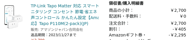
このシリーズはNode.jsとPythonのSDKがコミュニティーによってメンテされており、各種操作を自動化できますし、レスポンスも十分高速です
型番について少し補足をすると、
- P100は最もオーソドックスなスマートプラグ
- P110はスマートプラグにぶらさがっている機器の消費電力計測機能付き
- 末尾にMがついているものはMatter対応
を意味しますのでP110Mは令和最新版ですね
何かとお騒がせなTP-Link製品ですが、スマートプラグは家庭内ネットワークの根っこを握らせるタイプの機材ではないのであまり気にせず利用します
スマートプラグのAPI制御
スマートプラグのAPI制御をどこに置いたどんなマシンで処理するかは迷いどころですが、自宅内に常時起動しているLinux機がたまたまあったのでそこに置くことにします
何でサーバーを書くか、とにかくさらっと書くならNode.jsとPythonの二択です
Node.jsのランタイムサポート期間について考えるのが嫌だったのでPythonにしました
処理内容は至ってシンプルで、http.serverでお手軽HTTPサーバーを立ててリクエストを受け、リクエストが来たらPyP100ライブラリでスマートプラグを操作します
import os
from http.server import BaseHTTPRequestHandler, ThreadingHTTPServer
from PyP100 import PyP100
import throttle

ADDRESS = "192.168.0.157"
PORT = 4080

p100 = PyP100.P100("192.168.0.XXX", "TPLINK_ACCOUNT_ID", "TPLINK_PASSWORD") #Creates a P100 plug object

class MyHandler(BaseHTTPRequestHandler):
    @throttle.wrap(1, 1)
    def do_GET(self):
        self.send_response(200)
        self.send_header('Content-type', 'text/html')
        self.end_headers()
        message = "Hello, world!"
        self.wfile.write(bytes(message, "utf8"))
        print(self.path)
        p100.handshake() #Creates the cookies required for further methods
        p100.login() #Sends credentials to the plug and creates AES Key and IV for further methods
        p100.toggleState() #Toggles the state of the connected plug

        return

httpd = ThreadingHTTPServer((ADDRESS, PORT), MyHandler)
httpd.serve_forever()
コードについて
- PyP100の初期化用にターゲット機器のIPアドレスと制御用TP-LinkアカウントのID/パスワードが必要です
- Arduino側で500ms未満の間隔での複数回データ送信は抑制していますがボタンを長めに押した際は複数パケットが飛んできて電源がフリッカー的挙動をしてしまいイマイチなので
throttleパッケージのデコレータを利用して入力値をスロットルしています - 適当なmessageを返していて どうせATOM Lite側では読み捨てるので空でも良いのですが、200応答でレスポンスが空だと味気ないのでなんとなく返しています
この手のサーバープロセスを用意する場合直近状態値を(PC再起動やプロセス再起動を超えて)保持する方法に困るところがありますが、 p100.toggleState() を利用するとTapoのAPI側でいい感じにtoggle挙動をしてくれるので自前のプログラム側内部に状態を保存する必要がなくてラクです
スロットルの都合かたまにoffが効かないことがある気がしますがまあ許容というか、ダメそうならもう一回押せばよいと思える程度の頻度なので気にせずにいます
p100.login() のログイン結果をメモリ上へ保持して使いまわしたほうが実際のリクエストタイミングでのスマートプラグ操作を高速化できるのでは?と思いましたが、試してみるとこのままでも十分に高速だったのでHTTPリクエストハンドラ内で毎回処理しています
セッションキーを保持するとそれはそれでexpireの検出とリトライという厄介な問題が生じるので一旦このままで良いと思います
非公式SDKゆえの厄介さ
最近のP100系のアップデートによりPyP100ライブラリから認証トークンが取得できなくなったという報告があがっています
本稿の執筆中に突如手元でも認証トークンを取得できなくなったのですが、上記issueで言及されている↓のforkであれば問題ないことを手元でも確認しました
pip install git+https://github.com/almottier/TapoP100.git@main
として上書きインストールでOKでした
環境によっては既存のPyP100を削除する必要があるかもしれません
実際に動かす
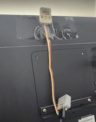
PCモニターの上にひょこっと赤外線送受信モジュールを配置し
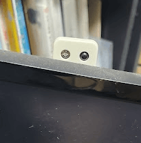
モニターの背中へ強力めなテープで貼ります
ATOM LiteはVESAマウント穴+3Dプリントした土台の上に載せました
特にトラブルなく使えています
消費電力削減効果だけで半年もあればP110Mの代金ぐらいは回収できるでしょう
サステナブルですね
たまに寝落ちなどしてモニターを消し忘れる問題はこの仕組みでは解決しないため、Tapoアプリ側の設定で毎日午前4時に強制電源Offするようにしました
4時をまたいで視聴し続けるのはおそらく年に1回ぐらいNetflixのシーズン一気見をするタイミングぐらいなので実用上は問題ないでしょう
追加検討事項
せっかくスマートプラグがMatter対応なのでMatterでちゃんと実装すれば初期設定時以外はTP-Linkのアカウントに縛られずイントラ操作で完結できそうですが、把握すべきMatter仕様規模が案外大きかったことに加えて、P100/110用のTP-Link側APIで十分にレスポンスが安定して速かったため今回はMatter利用を見送りました
スマートプラグ制御に関して外部のPythonプロセスへ依存するのは若干大掛かりであるためATOM Lite内部でTapo P110Mの制御まで完結させるパターンも考えましたが、認証用ペイロードの構成が大変そうで頑張りの割にメリットが少ないので「要たるインタフェース部分では単機能高性能へ注力し、機能の幅はリッチな環境で補うべし」という心の声に従ってATOM Lite側は赤外線信号を確実に拾う・レイテンシーをなるべく抑えてWi-Fi経由で転送することへフォーカスしました
ATOM Liteの消費電力について、USB-C消費電力計で計測したところほぼ常時計測範囲外、10秒に1秒ほど0.08A検出する程度だったので常時接続電源を利用するなら許容範囲と捉えてESP32のmodem sleep / light sleep類も未設定です
うまいこと赤外線パターンによるハードウェアトリガーを仕込めれば99%ほど省電力化できそうですが、頑張ってもWi-Fi APへの接続タイムラグがネックになって「1秒以内に電源状態へ反映」という要件を満たすのが困難になりそうなので思考をやめました
まとめ
Fire TVリモコンの発する赤外線信号をATOM Liteと赤外線モジュールで受けてTCPパケットへ詰め込むことで自由なモニター電源制御が可能になりました
Fire TV Stickシリーズ10年来のバグをfixできたので一安心です
Amazon本家でのfixをお待ちしております
Discussion