Ender 3をKlipper化する(8ビットコントローラ版)
手順
Ender 3の8ビットコントローラでKlipperを使うべくチャレンジしましたのでご紹介します。海外諸先輩方の資料を紐解きながら手順を踏襲しつつ多少アレンジも加えて成功しました。手順は次の1~4になります。他の機種と異なる点は、ファームウェア書き込み前にブートローダの書き込みが必要なことです。よくあるブートローダ書き込みの方法の記事と本稿との違いは、書き込みにArduinoを使わずRaspberry Piを使うことです。
- 準備
- ブートローダを書き込む
- Klipperファームウェアを書き込む
- Klipperの設定
では、順番に作業内容を説明します。
1. 準備
次のa~cを用意します。a,bは追加で入手が必要です。
a: マイコンボード(Raspberry Piなど)
ブートローダの書き込み、および、Klipper実行環境としてLinuxマイコンボードを使用します。ボードとOSは、あらかじめセットアップしておきます。
本稿ではRaspberry Pi Zero 2WにMainsailOSを入れて使用しています。他のマイコンやOSディストリビューションを使う場合は、適宜、読み替えをお願いします。
b: 配線用の電線
ブートローダの書き込み用に電線が必要です。ブレッドボード・ジャンパー延長ワイヤ(メス-メス)を使うと便利です。配線数は6本です。
本稿ではピンソケットにケーブルをはんだづけした手作りケーブルを使用しています。
c: Mini-USBケーブル
ファームウェアを書き込むためにUSBケーブルが必要です。Ender 3の付属品で構いません。
2. ブートローダを書き込む
コンパイル済のブートローダが公開されていますので、それをダウンロードし、ISP端子からボードへ書き込みます。詳しい手順を2.1~2.4で説明します。
2.1. ブートローダのダウンロード
sshでRaspberry Piにログインし、wgetコマンドを使って公開されているブートローダをダウンロードしておきます。
wget 'https://github.com/Lauszus/Sanguino/raw/1.0.2/bootloaders/optiboot/optiboot_atmega1284p.hex'
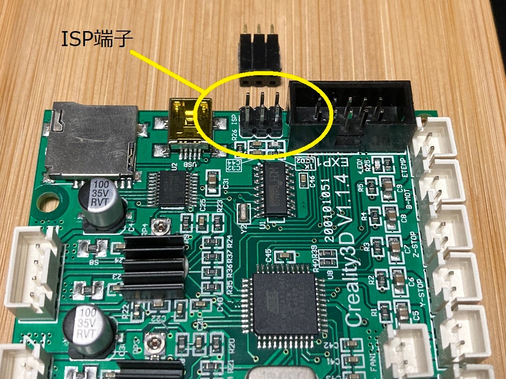
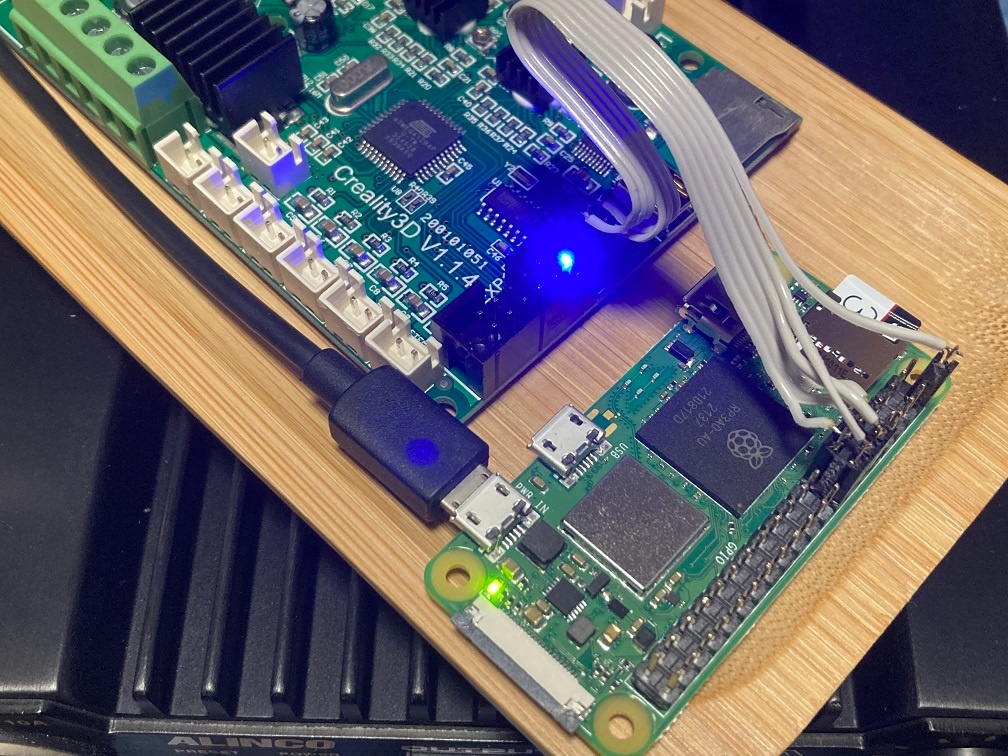
2.2. ISPの配線
Raspberry PiのGPIO端子と、Ender 3コントローラのISP(In-System Programming)端子を接続します。ISP端子はUSB端子の隣にあります。
ISP端子のピン配置は次のとおりです。
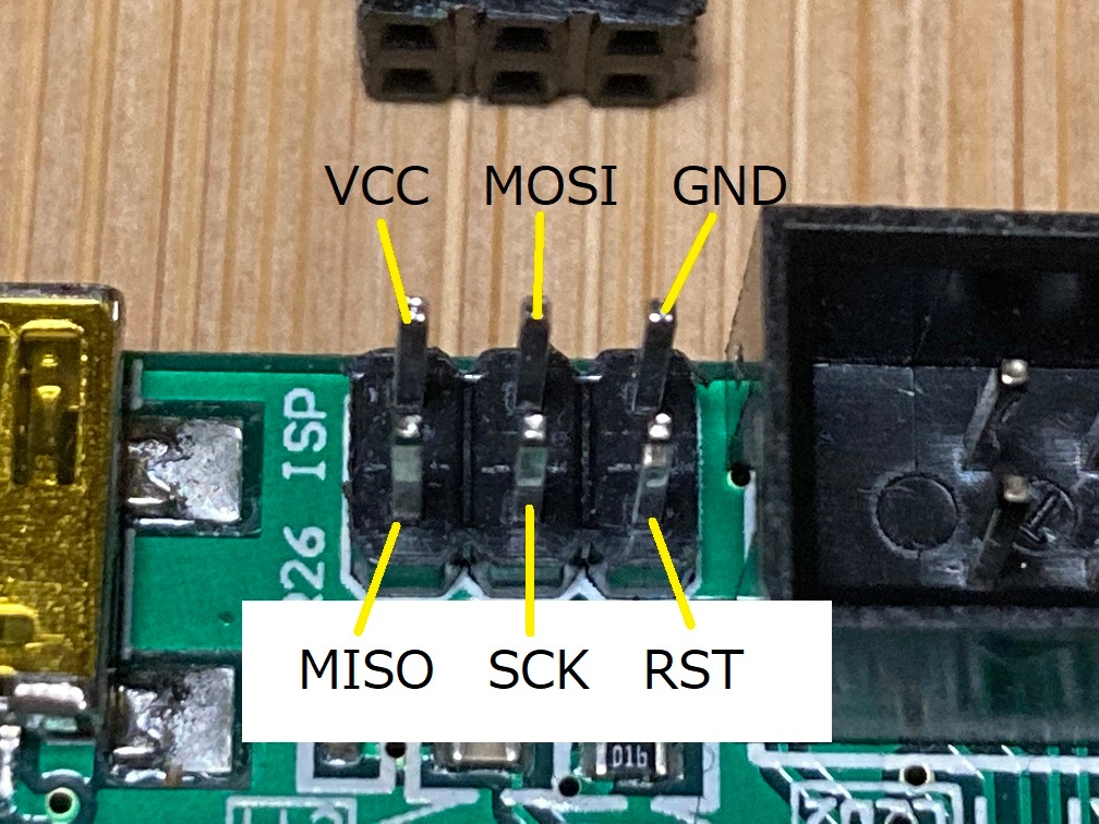
接続は次のとおり行います。
| ISP Pin No. | Ender 3 ISP 端子 | RasPi GPIO 端子 | GPIO Pin No. | |
|---|---|---|---|---|
| 1 | MISO | − | GPIO 17 | 11 |
| 2 | VCC | − | 5V | 2 |
| 3 | SCK | − | GPIO 27 | 13 |
| 4 | MOSI | − | GPIO 23 | 16 |
| 5 | RST | − | GPIO 22 | 15 |
| 6 | GND | − | GND | 14 |
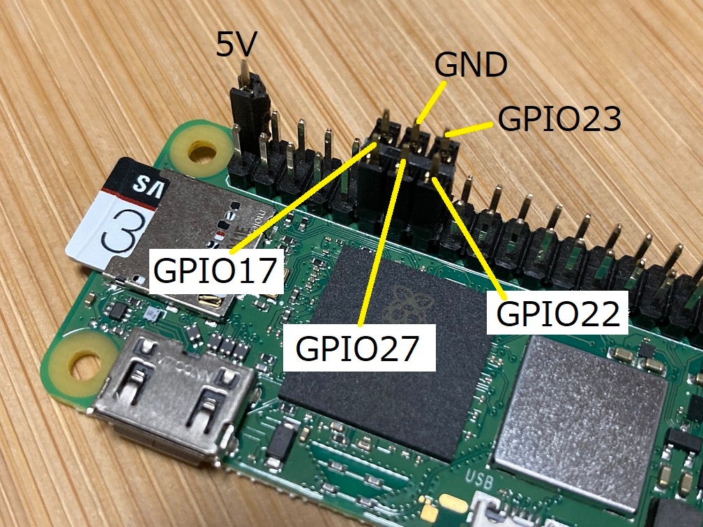
Raspberry Piのピン配置は次のとおりです。間違いがないように、Raspberry PiのGPIO端子の配置をリンク先資料で再確認してください。
2.3. avrdudeの設定
配線したらRaspberry Piの電源を入れます。Ender 3のコントローラにも電源が供給されます。
書き込みにはavrdudeコマンドを使用します。まだavrdudeがインストールされていない場合はインストールします。
sudo apt-get install avrdude
avrdudeの設定ファイルファイルをホームディレクトリへコピーします。
cp /etc/avrdude.conf ~/
コピーした設定ファイルをエディタで開き、末尾に設定を追加します。
nano ~/avrdude.conf
programmer
    id = "pi_isp";
    desc = "Use the Linux ISP interface to bitbang GPIO lines";
    type = "linuxgpio";
    reset = 22;
    sck = 27;
    mosi = 23;
    miso = 17;
;
設定ファイルを保存します。
続いて、avrdudeがEnder 3コントローラと実際に通信できることをテストします。
sudo avrdude -p atmega1284p -C ~/avrdude.conf -c pi_isp -v
文字がたくさん表示されますが、その中に、次のような出力が得られたら正しく動作しています。
avrdude: AVR device initialized and ready to accept instructions

Reading | ################################################## | 100% 0.00s

avrdude: Device signature = 0x1e9705 (probably m1284p)
全ての画面出力(クリックで開く)
avrdude: Version 6.3-20171130
         Copyright (c) 2000-2005 Brian Dean, http://www.bdmicro.com/
         Copyright (c) 2007-2014 Joerg Wunsch

         System wide configuration file is "/home/pi/avrdude.conf"
         User configuration file is "/root/.avrduderc"
         User configuration file does not exist or is not a regular file, skipping

         Using Port                    : unknown
         Using Programmer              : pi_1
         AVR Part                      : ATmega1284P
         Chip Erase delay              : 55000 us
         PAGEL                         : PD7
         BS2                           : PA0
         RESET disposition             : dedicated
         RETRY pulse                   : SCK
         serial program mode           : yes
         parallel program mode         : yes
         Timeout                       : 200
         StabDelay                     : 100
         CmdexeDelay                   : 25
         SyncLoops                     : 32
         ByteDelay                     : 0
         PollIndex                     : 3
         PollValue                     : 0x53
         Memory Detail                 :

                                  Block Poll               Page                       Polled
           Memory Type Mode Delay Size  Indx Paged  Size   Size #Pages MinW  MaxW   ReadBack
           ----------- ---- ----- ----- ---- ------ ------ ---- ------ ----- ----- ---------
           eeprom        65    10   128    0 no       4096    8      0  9000  9000 0xff 0xff
           flash         65    10   256    0 yes    131072  256    512  4500  4500 0xff 0xff
           lock           0     0     0    0 no          1    0      0  9000  9000 0x00 0x00
           lfuse          0     0     0    0 no          1    0      0  9000  9000 0x00 0x00
           hfuse          0     0     0    0 no          1    0      0  9000  9000 0x00 0x00
           efuse          0     0     0    0 no          1    0      0  9000  9000 0x00 0x00
           signature      0     0     0    0 no          3    0      0     0     0 0x00 0x00
           calibration    0     0     0    0 no          1    0      0     0     0 0x00 0x00

         Programmer Type : linuxgpio
         Description     : Use the Linux sysfs interface to bitbang GPIO lines
         Pin assignment  : /sys/class/gpio/gpio{n}
           RESET   =  22
           SCK     =  27
           MOSI    =  23
           MISO    =  17

avrdude: AVR device initialized and ready to accept instructions

Reading | ################################################## | 100% 0.00s

avrdude: Device signature = 0x1e9705 (probably m1284p)
avrdude: safemode: lfuse reads as D6
avrdude: safemode: hfuse reads as DC
avrdude: safemode: efuse reads as FD

avrdude: safemode: lfuse reads as D6
avrdude: safemode: hfuse reads as DC
avrdude: safemode: efuse reads as FD
avrdude: safemode: Fuses OK (E:FD, H:DC, L:D6)

avrdude done.  Thank you.
2.4. ブートローダの書き込み
Ender 3コントローラボードにブートローダを書き込みます。
sudo avrdude -p atmega1284p -C ~/avrdude.conf -c pi_isp -v -U flash:w:optiboot_atmega1284p.hex:i
文字がたくさん出力されますが、その中に、次のような出力が得られたら正常に書き込みができています。
Writing | ################################################## | 100% 0.20s

avrdude: 131072 bytes of flash written

(中略)

Reading | ################################################## | 100% 0.18s

avrdude: verifying ...
avrdude: 131072 bytes of flash verified
全ての画面出力(クリックで開く)
avrdude: Version 6.3-20171130
         Copyright (c) 2000-2005 Brian Dean, http://www.bdmicro.com/
         Copyright (c) 2007-2014 Joerg Wunsch

         System wide configuration file is "/home/pi/avrdude.conf"
         User configuration file is "/root/.avrduderc"
         User configuration file does not exist or is not a regular file, skipping

         Using Port                    : unknown
         Using Programmer              : pi_1
         AVR Part                      : ATmega1284P
         Chip Erase delay              : 55000 us
         PAGEL                         : PD7
         BS2                           : PA0
         RESET disposition             : dedicated
         RETRY pulse                   : SCK
         serial program mode           : yes
         parallel program mode         : yes
         Timeout                       : 200
         StabDelay                     : 100
         CmdexeDelay                   : 25
         SyncLoops                     : 32
         ByteDelay                     : 0
         PollIndex                     : 3
         PollValue                     : 0x53
         Memory Detail                 :

                                  Block Poll               Page                       Polled
           Memory Type Mode Delay Size  Indx Paged  Size   Size #Pages MinW  MaxW   ReadBack
           ----------- ---- ----- ----- ---- ------ ------ ---- ------ ----- ----- ---------
           eeprom        65    10   128    0 no       4096    8      0  9000  9000 0xff 0xff
           flash         65    10   256    0 yes    131072  256    512  4500  4500 0xff 0xff
           lock           0     0     0    0 no          1    0      0  9000  9000 0x00 0x00
           lfuse          0     0     0    0 no          1    0      0  9000  9000 0x00 0x00
           hfuse          0     0     0    0 no          1    0      0  9000  9000 0x00 0x00
           efuse          0     0     0    0 no          1    0      0  9000  9000 0x00 0x00
           signature      0     0     0    0 no          3    0      0     0     0 0x00 0x00
           calibration    0     0     0    0 no          1    0      0     0     0 0x00 0x00

         Programmer Type : linuxgpio
         Description     : Use the Linux sysfs interface to bitbang GPIO lines
         Pin assignment  : /sys/class/gpio/gpio{n}
           RESET   =  22
           SCK     =  27
           MOSI    =  23
           MISO    =  17

avrdude: AVR device initialized and ready to accept instructions

Reading | ################################################## | 100% 0.00s

avrdude: Device signature = 0x1e9705 (probably m1284p)
avrdude: safemode: lfuse reads as D6
avrdude: safemode: hfuse reads as DC
avrdude: safemode: efuse reads as FD
avrdude: NOTE: "flash" memory has been specified, an erase cycle will be performed
         To disable this feature, specify the -D option.
avrdude: erasing chip
avrdude: reading input file "optiboot_atmega1284p.hex"
avrdude: writing flash (131072 bytes):

Writing | ################################################## | 100% 0.20s

avrdude: 131072 bytes of flash written
avrdude: verifying flash memory against optiboot_atmega1284p.hex:
avrdude: load data flash data from input file optiboot_atmega1284p.hex:
avrdude: input file optiboot_atmega1284p.hex contains 131072 bytes
avrdude: reading on-chip flash data:

Reading | ################################################## | 100% 0.18s

avrdude: verifying ...
avrdude: 131072 bytes of flash verified

avrdude: safemode: lfuse reads as D6
avrdude: safemode: hfuse reads as DC
avrdude: safemode: efuse reads as FD
avrdude: safemode: Fuses OK (E:FD, H:DC, L:D6)

avrdude done.  Thank you.
3. Klipperファームウェアを書き込む
初めにコンパイルを行い、次に書き込みます。詳しい手順を3.1〜3.3で説明します。
3.1. ファームウェアのコンパイル
Klipperのインストールディレクトリで、make menuconfigを実行します。
cd ~/klipper
make menuconfig
次の2か所を設定します。
- Micro-controller Architecture: Atmega AVR
- Processor model: atmega1284p
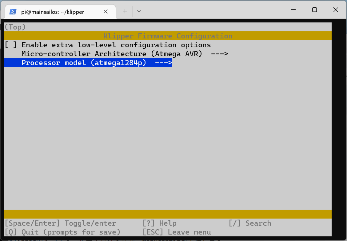
終わったら「Q」キーを押して終了します。makeしてファームウェアをコンパイルします。
make
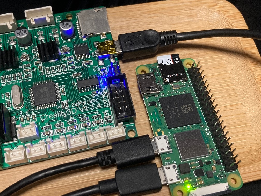
3.2. USB接続
Raspberry PiとEnder 3コントローラをUSBケーブルで接続します。
デバイスファイルの名前を見つけます。
ls /dev/serial/by-id/
本稿ではusb-1a86_USB_Serial-if00-port0という名前のファイルがありました。フルパスのデバイスファイル名は次のようになります。
/dev/serial/by-id/usb-1a86_USB_Serial-if00-port0
3.3. ファームウェアの書き込み
次のコマンドを実行してファームウェアを書き込みます。先ほどのデバイスファイル名を指定します。
make flash FLASH_DEVICE=/dev/serial/by-id/usb-1a86_USB_Serial-if00-port0
次のような出力が得られたら正常に書き込みができています。
  Flashing out/klipper.elf.hex to /dev/serial/by-id/usb-1a86_USB_Serial-if00-port0 via avrdude

avrdude: AVR device initialized and ready to accept instructions

Reading | ################################################## | 100% 0.00s

avrdude: Device signature = 0x1e9705 (probably m1284p)
avrdude: reading input file "out/klipper.elf.hex"
avrdude: writing flash (29456 bytes):

Writing | ################################################## | 100% 3.96s

avrdude: 29456 bytes of flash written
avrdude: verifying flash memory against out/klipper.elf.hex:
avrdude: load data flash data from input file out/klipper.elf.hex:
avrdude: input file out/klipper.elf.hex contains 29456 bytes
avrdude: reading on-chip flash data:

Reading | ################################################## | 100% 3.34s

avrdude: verifying ...
avrdude: 29456 bytes of flash verified

avrdude: safemode: Fuses OK (E:00, H:00, L:00)

avrdude done.  Thank you.
4. Klipperの設定
Klipper本家の設定サンプルをベースにしてprinter.cfgを作成します。
変更するべき点は、[mcu]セクションのserialに、先ほどのデバイスファイル名を指定することです。他の設定はサンプルのままで動作します。
[mcu]
serial: /dev/serial/by-id/usb-1a86_USB_Serial-if00-port0
参考までに、本稿でテスト用として使用しているprinter.cfgを示します。
# This file contains common pin mappings for the 2018 Creality
# Ender 3. To use this config, the firmware should be compiled for the
# AVR atmega1284p.

# Note, a number of Melzi boards are shipped with a bootloader that
# requires the following command to flash the board:
#  avrdude -p atmega1284p -c arduino -b 57600 -P /dev/ttyUSB0 -U out/klipper.elf.hex
# If the above command does not work and "make flash" does not work
# then one may need to flash a bootloader to the board - see the
# Klipper docs/Bootloaders.md file for more information.

# See docs/Config_Reference.md for a description of parameters.

[pause_resume]

[virtual_sdcard]
path: ~/gcode_files

[stepper_x]
step_pin: PD7
dir_pin: !PC5
enable_pin: !PD6
microsteps: 16
rotation_distance: 40
endstop_pin: ^PC2
position_endstop: 0
position_max: 235
homing_speed: 50

[stepper_y]
step_pin: PC6
dir_pin: !PC7
enable_pin: !PD6
microsteps: 16
rotation_distance: 40
endstop_pin: ^PC3
position_endstop: 0
position_max: 235
homing_speed: 50

[stepper_z]
step_pin: PB3
dir_pin: PB2
enable_pin: !PA5
microsteps: 16
rotation_distance: 8
endstop_pin: ^PC4
position_endstop: 0.0
position_max: 250

[extruder]
max_extrude_only_distance: 100.0
step_pin: PB1
dir_pin: !PB0
enable_pin: !PD6
microsteps: 16
rotation_distance: 33.683
nozzle_diameter: 0.400
filament_diameter: 1.750
heater_pin: PD5
sensor_type: EPCOS 100K B57560G104F
sensor_pin: PA7
control: pid
# tuned for stock hardware with 200 degree Celsius target
pid_Kp: 21.527
pid_Ki: 1.063
pid_Kd: 108.982
min_temp: -257
max_temp: 250
min_extrude_temp: -257

[heater_bed]
heater_pin: PD4
sensor_type: EPCOS 100K B57560G104F
sensor_pin: PA6
control: pid
# tuned for stock hardware with 50 degree Celsius target
pid_Kp: 54.027
pid_Ki: 0.770
pid_Kd: 948.182
min_temp: -257
max_temp: 130

[fan]
pin: PB4

[mcu]
serial: /dev/serial/by-id/usb-1a86_USB_Serial-if00-port0

[printer]
kinematics: cartesian
max_velocity: 300
max_accel: 3000
max_z_velocity: 5
max_z_accel: 100

[bed_screws]
screw1: 30.5, 37
screw2: 30.5, 207
screw3: 204.5, 207
screw4: 204.5, 37

[display]
lcd_type: st7920
cs_pin: PA3
sclk_pin: PA1
sid_pin: PC1
encoder_pins: ^PD2, ^PD3
click_pin: ^!PC0

# The print bed can move so far to the front, that the nozzle can reach the
# plastic cover of the print bed heater cable (only when the bed is moved by
# hand). By homing the Y axis before the X axis, it is ensured the nozzle will
# not melt through the plastic part.
# BEWARE: You will lose the ability to home axes individually. The printer will
# always home all axes for every G28 command.
#[homing_override]
#gcode:
# G28 Y0
# G28 X0
# G28 Z0
以上の手順で、Ender 3の8ビットコントローラに、Klipperをインストールすることができます。
Discussion