メモ: 『Linuxで動かしながら学ぶTCP/IPネットワーク入門』
Amazon: https://www.amazon.co.jp/dp/B085BG8CH5/
著者の方: もみじあめさん https://twitter.com/momijiame
サポートページ: https://github.com/momijiame/linux-tcpip-book
- Amazonで個人出版されてる本なのか特に出版社などの情報はなかった
- 写経などはrootユーザーでやってるのでsudoをつけてないので注意
ネットワーク勉強まとめのスクラップ:
3章 Network Namespace - 1
helloworld
-
ip netnsコマンドでNetworkNamespaceの作成や操作が可能になる - 作成したNetworkNamespace内で独自のネットワークを構築できる
$ ip netns add helloworld
$ ip netns list
helloworld

$ ip netns exec helloworld ip addr show
1: lo: <LOOPBACK> mtu 65536 qdisc noop state DOWN group default qlen 1000
    link/loopback 00:00:00:00:00:00 brd 00:00:00:00:00:00

$ ip netns delete helloworld
NetworkNamespaceをつなげる
こういうのを作るらしい
# NSを作成
$ ip netns add ns1
$ ip netns add ns2

# 仮想ネットワークインターフェイスを追加
# ネットワークインターフェイスは ns1-veth0 ns2-veth0 のように2つで1組として作成される
$ ip link add ns1-veth0 type veth peer name ns2-veth0

# 確認
$ ip link show | grep veth
7: ns2-veth0@ns1-veth0: <BROADCAST,MULTICAST,M-DOWN> mtu 1500 qdisc noop state DOWN mode DEFAULT group default qlen 1000
8: ns1-veth0@ns2-veth0: <BROADCAST,MULTICAST,M-DOWN> mtu 1500 qdisc noop state DOWN mode DEFAULT group default qlen 1000

# 仮想ネットワークインターフェイスをNetwork Namespaceで使えるようにする
$ ip link set ns1-veth0 netns ns1
$ ip link set ns2-veth0 netns ns2

# 確認
$ ip link show | grep veth

$ ip netns exec ns1 ip link show | grep veth
8: ns1-veth0@if7: <BROADCAST,MULTICAST> mtu 1500 qdisc noop state DOWN mode DEFAULT group default qlen 1000

$ ip netns exec ns2 ip link show | grep veth
7: ns2-veth0@if8: <BROADCAST,MULTICAST> mtu 1500 qdisc noop state DOWN mode DEFAULT group default qlen 1000

# IP使って通信可能にするためにIPアドレスを付与
$ ip netns exec ns1 ip addr add 192.0.2.1/24 dev ns1-veth0
$ ip netns exec ns2 ip addr add 192.0.2.2/24 dev ns2-veth0

$ ip netns exec ns1 ip link show ns1-veth0 | grep state
8: ns1-veth0@if7: <BROADCAST,MULTICAST> mtu 1500 qdisc noop state DOWN mode DEFAULT group default qlen 1000

$ ip netns exec ns2 ip link show ns2-veth0 | grep state
7: ns2-veth0@if8: <BROADCAST,MULTICAST> mtu 1500 qdisc noop state DOWN mode DEFAULT group default qlen 1000

# ネットワークインターフェイスをUP状態にして、利用可能にする
# ↑で確認したやつで state DOWN となっていてDOWN状態であることが確認できる
$ ip netns exec ns1 ip link set ns1-veth0 up
$ ip netns exec ns2 ip link set ns2-veth0 up

# 通信できるか確認
$ ip netns exec ns1 ping -c 3 192.0.2.2
PING 192.0.2.2 (192.0.2.2) 56(84) bytes of data.
64 bytes from 192.0.2.2: icmp_seq=1 ttl=64 time=0.039 ms
64 bytes from 192.0.2.2: icmp_seq=2 ttl=64 time=0.029 ms
64 bytes from 192.0.2.2: icmp_seq=3 ttl=64 time=0.030 ms

--- 192.0.2.2 ping statistics ---
3 packets transmitted, 3 received, 0% packet loss, time 2063ms
rtt min/avg/max/mdev = 0.029/0.032/0.039/0.008 ms


# NSを削除してクリーンアップ
$ ip netns delete ns1
$ ip netns delete ns2
3章 Network Namespace - 2
ルーターを入れる
ネットワークとホスト
192.0.1.1/24をネットワークとホストに分解すると以下のようになる
/24のCIDRがどのビットからネットワークとホストに分解するかを決めてる
こういうのを作るらしい
# NSを作成
$ ip netns add ns1
$ ip netns add ns2
$ ip netns add router

# NSを確認
$ ip netns list
router
ns2
ns1

# 仮想ネットワークインターフェイスを追加
$ ip link add ns1-veth0 type veth peer name gw-veth0
$ ip link add ns2-veth0 type veth peer name gw-veth1

# 仮想ネットワークインターフェイスをNetwork Namespaceで使えるようにする
$ ip link set ns1-veth0 netns ns1
$ ip link set ns2-veth0 netns ns2
$ ip link set gw-veth0 netns router
$ ip link set gw-veth1 netns router

# ネットワークインターフェイスをUP状態にして、利用可能にする
$ ip netns exec ns1 ip link set ns1-veth0 up
$ ip netns exec ns2 ip link set ns2-veth0 up
$ ip netns exec router ip link set gw-veth0 up
$ ip netns exec router ip link set gw-veth1 up

# IP使って通信可能にするためにIPアドレスを付与してデフォルトゲートウェイを設定 - 1
$ ip netns exec ns1 ip addr add 192.0.2.1/24 dev ns1-veth0
$ ip netns exec router ip addr add 192.0.2.254/24 dev gw-veth0

# IP使って通信可能にするためにIPアドレスを付与デフォルトゲートウェイを設定 - 2
$ ip netns exec ns2 ip addr add 198.51.100.1/24 dev ns2-veth0
$ ip netns exec router ip addr add 198.51.100.254/24 dev gw-veth1
動作確認
# 通信できるか確認
$ ip netns exec ns1 ping -c 3 192.0.2.254
PING 192.0.2.254 (192.0.2.254) 56(84) bytes of data.
64 bytes from 192.0.2.254: icmp_seq=1 ttl=64 time=0.036 ms
64 bytes from 192.0.2.254: icmp_seq=2 ttl=64 time=0.025 ms
64 bytes from 192.0.2.254: icmp_seq=3 ttl=64 time=0.020 ms

--- 192.0.2.254 ping statistics ---
3 packets transmitted, 3 received, 0% packet loss, time 2033ms
rtt min/avg/max/mdev = 0.020/0.027/0.036/0.006 ms

$ ip netns exec ns2 ping -c 3 198.51.100.254
PING 198.51.100.254 (198.51.100.254) 56(84) bytes of data.
64 bytes from 198.51.100.254: icmp_seq=1 ttl=64 time=0.038 ms
64 bytes from 198.51.100.254: icmp_seq=2 ttl=64 time=0.029 ms
64 bytes from 198.51.100.254: icmp_seq=3 ttl=64 time=0.030 ms

--- 198.51.100.254 ping statistics ---
3 packets transmitted, 3 received, 0% packet loss, time 2081ms
rtt min/avg/max/mdev = 0.029/0.032/0.038/0.006 ms


# この状態だとまだルーター越しの通信ができない
$ ip netns exec ns1 ping -c 3 198.51.100.1 -I 192.0.2.1
PING 198.51.100.1 (198.51.100.1) from 192.0.2.1 : 56(84) bytes of data.
ping: sendmsg: ネットワークに届きません
ping: sendmsg: ネットワークに届きません
ping: sendmsg: ネットワークに届きません

--- 198.51.100.1 ping statistics ---
3 packets transmitted, 0 received, 100% packet loss, time 2065ms

# ルーティングテーブルを確認
# 198.51.100.1を処理するルーティングテーブルが無いことがわかる
$ ip netns exec ns1 ip route show
192.0.2.0/24 dev ns1-veth0 proto kernel scope link src 192.0.2.1
デフォルトルートを追加
# ns1/ns2それぞれのデフォルトルートにrouterを設定
$ ip netns exec ns1 ip route add default via 192.0.2.254
$ ip netns exec ns2 ip route add default via 198.51.100.254

# この状態で動作確認するとネットワークに届くようになるば、packet lossとなる
$ ip netns exec ns1 ping -c 3 198.51.100.1 -I 192.0.2.1
PING 198.51.100.1 (198.51.100.1) from 192.0.2.1 : 56(84) bytes of data.

--- 198.51.100.1 ping statistics ---
3 packets transmitted, 0 received, 100% packet loss, time 2024ms

# 以下のコマンドによってLinuxをIPv4ルーターとして動作させるようにする
# 環境によってはデフォルトで net.ipv4.ip_forward=1 となってることもある
# その状態であえて失敗させるようにする場合は ip netns exec router sysctl net.ipv4.ip_forward=0 コマンドを実行する
$ ip netns exec router sysctl net.ipv4.ip_forward=1

# これでpingするとようやく返事が帰ってくるようになる
$ ip netns exec ns1 ping -c 3 198.51.100.1 -I 192.0.2.1
PING 198.51.100.1 (198.51.100.1) from 192.0.2.1 : 56(84) bytes of data.
64 bytes from 198.51.100.1: icmp_seq=1 ttl=63 time=0.050 ms
64 bytes from 198.51.100.1: icmp_seq=2 ttl=63 time=0.049 ms
64 bytes from 198.51.100.1: icmp_seq=3 ttl=63 time=0.039 ms

--- 198.51.100.1 ping statistics ---
3 packets transmitted, 3 received, 0% packet loss, time 2045ms
rtt min/avg/max/mdev = 0.039/0.046/0.050/0.005 ms

# router NSのrouteをみるとこのようになっている
# ns1からns2へのpingだとrouterが198.51.100.1への宛先の際に198.51.100.0/24をみるようになって通信できるようになるということ?
$ ip netns exec router ip route show
192.0.2.0/24 dev gw-veth0 proto kernel scope link src 192.0.2.254
198.51.100.0/24 dev gw-veth1 proto kernel scope link src 198.51.100.254


# NSを削除してクリーンアップ
$ ip netns delete ns1
$ ip netns delete ns2
$ ip netns delete router
3章 Network Namespace - 3
ルーターを2台にする
こういうのを作るらしい
# NSを作成
$ ip netns add ns1
$ ip netns add ns2
$ ip netns add router1
$ ip netns add router2

# 仮想ネットワークインターフェイスを追加
$ ip link add ns1-veth0 type veth peer name gw1-veth0
$ ip link add gw1-veth1 type veth peer name gw2-veth0
$ ip link add gw2-veth1 type veth peer name ns2-veth0

# 仮想ネットワークインターフェイスをNetwork Namespaceで使えるようにする
$ ip link set ns1-veth0 netns ns1
$ ip link set ns2-veth0 netns ns2
$ ip link set gw1-veth0 netns router1
$ ip link set gw1-veth1 netns router1
$ ip link set gw2-veth0 netns router2
$ ip link set gw2-veth1 netns router2

# ネットワークインターフェイスをUP状態にして、利用可能にする
$ ip netns exec ns1 ip link set ns1-veth0 up
$ ip netns exec ns2 ip link set ns2-veth0 up
$ ip netns exec router1 ip link set gw1-veth0 up
$ ip netns exec router1 ip link set gw1-veth1 up
$ ip netns exec router2 ip link set gw2-veth0 up
$ ip netns exec router2 ip link set gw2-veth1 up

# IP使って通信可能にするためにIPアドレスを付与
$ ip netns exec ns1 ip addr add 192.0.2.1/24 dev ns1-veth0
$ ip netns exec router1 ip addr add 192.0.2.254/24 dev gw1-veth0
$ ip netns exec router1 ip addr add 203.0.113.1/24 dev gw1-veth1
$ ip netns exec router2 ip addr add 203.0.113.2/24 dev gw2-veth0
$ ip netns exec router2 ip addr add 198.51.100.254/24 dev gw2-veth1
$ ip netns exec ns2 ip addr add 198.51.100.1/24 dev ns2-veth0

# ns1/ns2それぞれのデフォルトルートにrouterを設定
$ ip netns exec ns1 ip route add default via 192.0.2.254
$ ip netns exec ns2 ip route add default via 198.51.100.254

# router1/router2をそれぞれIPv4ルーター化
$ ip netns exec router1 sysctl net.ipv4.ip_forward=1
$ ip netns exec router2 sysctl net.ipv4.ip_forward=1

# 今回はrouterが2台あるのでrouter同士の通信経路を登録するためにルーティングエントリーを追加
$ ip netns exec router1 ip route add 198.51.100.0/24 via 203.0.113.2
$ ip netns exec router2 ip route add 192.0.2.0/24 via 203.0.113.1

# 設定確認
$ ip netns exec router1 ip route show
192.0.2.0/24 dev gw1-veth0 proto kernel scope link src 192.0.2.254
198.51.100.0/24 via 203.0.113.2 dev gw1-veth1
203.0.113.0/24 dev gw1-veth1 proto kernel scope link src 203.0.113.1

$ ip netns exec router2 ip route show
192.0.2.0/24 via 203.0.113.1 dev gw2-veth0
198.51.100.0/24 dev gw2-veth1 proto kernel scope link src 198.51.100.254
203.0.113.0/24 dev gw2-veth0 proto kernel scope link src 203.0.113.2

# 動作確認
$ ip netns exec ns1 ping -c 3 198.51.100.1 -I 192.0.2.1
PING 198.51.100.1 (198.51.100.1) from 192.0.2.1 : 56(84) bytes of data.
64 bytes from 198.51.100.1: icmp_seq=1 ttl=62 time=0.060 ms
64 bytes from 198.51.100.1: icmp_seq=2 ttl=62 time=0.040 ms
64 bytes from 198.51.100.1: icmp_seq=3 ttl=62 time=0.038 ms

--- 198.51.100.1 ping statistics ---
3 packets transmitted, 3 received, 0% packet loss, time 2026ms
rtt min/avg/max/mdev = 0.038/0.046/0.060/0.009 ms

$ ip netns exec ns2 ping -c 3 192.0.2.1 -I 198.51.100.1
PING 192.0.2.1 (192.0.2.1) from 198.51.100.1 : 56(84) bytes of data.
64 bytes from 192.0.2.1: icmp_seq=1 ttl=62 time=0.041 ms
64 bytes from 192.0.2.1: icmp_seq=2 ttl=62 time=0.043 ms
64 bytes from 192.0.2.1: icmp_seq=3 ttl=62 time=0.044 ms

--- 192.0.2.1 ping statistics ---
3 packets transmitted, 3 received, 0% packet loss, time 2068ms
rtt min/avg/max/mdev = 0.041/0.042/0.044/0.007 ms


# NSを削除してクリーンアップ
$ ip netns delete ns1
$ ip netns delete ns2
$ ip netns delete router1
$ ip netns delete router2
4章 イーサネット - 1
検証用の環境を作成
作る環境はNetwork Namespaceの始めの方で作ったのと同じような環境
# NSを作成
$ ip netns add ns1
$ ip netns add ns2

# 仮想ネットワークインターフェイスを追加
$ ip link add ns1-veth0 type veth peer name ns2-veth0

# 仮想ネットワークインターフェイスをNetwork Namespaceで使えるようにする
$ ip link set ns1-veth0 netns ns1
$ ip link set ns2-veth0 netns ns2

# ネットワークインターフェイスをUP状態にして、利用可能にする
$ ip netns exec ns1 ip link set ns1-veth0 up
$ ip netns exec ns2 ip link set ns2-veth0 up

# IP使って通信可能にするためにIPアドレスを付与
$ ip netns exec ns1 ip addr add 192.0.2.1/24 dev ns1-veth0
$ ip netns exec ns2 ip addr add 192.0.2.2/24 dev ns2-veth0

# 動作確認
$ ip netns exec ns1 ping -c 3 192.0.2.2
PING 192.0.2.2 (192.0.2.2) 56(84) bytes of data.
64 bytes from 192.0.2.2: icmp_seq=1 ttl=64 time=0.050 ms
64 bytes from 192.0.2.2: icmp_seq=2 ttl=64 time=0.028 ms
64 bytes from 192.0.2.2: icmp_seq=3 ttl=64 time=0.030 ms

--- 192.0.2.2 ping statistics ---
3 packets transmitted, 3 received, 0% packet loss, time 2066ms
rtt min/avg/max/mdev = 0.028/0.036/0.050/0.009 ms

$ ip netns exec ns2 ping -c 3 192.0.2.1
PING 192.0.2.1 (192.0.2.1) 56(84) bytes of data.
64 bytes from 192.0.2.1: icmp_seq=1 ttl=64 time=0.022 ms
64 bytes from 192.0.2.1: icmp_seq=2 ttl=64 time=0.029 ms
64 bytes from 192.0.2.1: icmp_seq=3 ttl=64 time=0.027 ms

--- 192.0.2.1 ping statistics ---
3 packets transmitted, 3 received, 0% packet loss, time 2062ms
rtt min/avg/max/mdev = 0.022/0.026/0.029/0.003 ms
今回はイーサネット観察をやりやすくするためにMACアドレスも設定
# MACアドレスを設定
$ ip netns exec ns1 ip link set dev ns1-veth0 address 00:00:5E:00:53:01
$ ip netns exec ns2 ip link set dev ns2-veth0 address 00:00:5E:00:53:02

# 設定されたMACアドレスを確認
$ ip netns exec ns1 ip link show | grep link/ether
    link/ether 00:00:5e:00:53:01 brd ff:ff:ff:ff:ff:ff link-netns ns2
$ ip netns exec ns2 ip link show | grep link/ether
    link/ether 00:00:5e:00:53:02 brd ff:ff:ff:ff:ff:ff link-netns ns1
別ターミナルでパケットキャプチャ
$ ip netns exec ns1 tcpdump -tnel -i ns1-veth0 icmp
今回使ったtcpdumpのオプション
$ man tcpdump
...
-t     Don't print a timestamp on each dump line.
-n     Don't convert host addresses to names.  This can be used to avoid DNS lookups.
-e     Print the link-level header on each dump line.  This can be used, for example, to print MAC layer  addresses  for  protocols such as Ethernet and IEEE 802.11.
-l     Make stdout line buffered.  Useful if you want to see the data while capturing it.  E.g.,

                     tcpdump -l | tee dat

              or

                     tcpdump -l > dat & tail -f dat

              Note that on Windows,``line buffered'' means ``unbuffered'', so that WinDump will write each character individually if -l is
              specified.
-i interface
       --interface=interface
              Listen  on  interface.   If  unspecified,  tcpdump searches the system interface list for the lowest numbered, configured up
              interface (excluding loopback), which may turn out to be, for example, ``eth0''.

              On Linux systems with 2.2 or later kernels, an interface argument of ``any'' can be used to capture packets from all  inter‐
              faces.  Note that captures on the ``any'' device will not be done in promiscuous mode.

              If the -D flag is supported, an interface number as printed by that flag can be used as the interface argument, if no inter‐
              face on the system has that number as a name.
もう片方でpingを実行
$ ip netns exec ns1 ping -c 3 192.0.2.2 -I 192.0.2.1
PING 192.0.2.2 (192.0.2.2) from 192.0.2.1 : 56(84) bytes of data.
64 bytes from 192.0.2.2: icmp_seq=1 ttl=64 time=0.053 ms
64 bytes from 192.0.2.2: icmp_seq=2 ttl=64 time=0.039 ms
64 bytes from 192.0.2.2: icmp_seq=3 ttl=64 time=0.038 ms

--- 192.0.2.2 ping statistics ---
3 packets transmitted, 3 received, 0% packet loss, time 2063ms
rtt min/avg/max/mdev = 0.038/0.043/0.053/0.008 ms
tcpdump側での出力
$ ip netns exec ns1 tcpdump -tnel -i  ns1-veth0 icmp
dropped privs to tcpdump
tcpdump: verbose output suppressed, use -v or -vv for full protocol decode
listening on ns1-veth0, link-type EN10MB (Ethernet), capture size 262144 bytes
00:00:5e:00:53:01 > 00:00:5e:00:53:02, ethertype IPv4 (0x0800), length 98: 192.0.2.1 > 192.0.2.2: ICMP echo request, id 64371, seq 1, length 64
00:00:5e:00:53:02 > 00:00:5e:00:53:01, ethertype IPv4 (0x0800), length 98: 192.0.2.2 > 192.0.2.1: ICMP echo reply, id 64371, seq 1, length 64
00:00:5e:00:53:01 > 00:00:5e:00:53:02, ethertype IPv4 (0x0800), length 98: 192.0.2.1 > 192.0.2.2: ICMP echo request, id 64371, seq 2, length 64
00:00:5e:00:53:02 > 00:00:5e:00:53:01, ethertype IPv4 (0x0800), length 98: 192.0.2.2 > 192.0.2.1: ICMP echo reply, id 64371, seq 2, length 64
00:00:5e:00:53:01 > 00:00:5e:00:53:02, ethertype IPv4 (0x0800), length 98: 192.0.2.1 > 192.0.2.2: ICMP echo request, id 64371, seq 3, length 64
00:00:5e:00:53:02 > 00:00:5e:00:53:01, ethertype IPv4 (0x0800), length 98: 192.0.2.2 > 192.0.2.1: ICMP echo reply, id 64371, seq 3, length 64
tcpdumpで -e オプションを付けたことで 00:00:5e:00:53:01 > 00:00:5e:00:53:02, ethertype IPv4 (0x0800), length のようにMACアドレス情報が追加されている
-e オプション無しバージョン
$ ip netns exec ns1 tcpdump -tnl -i  ns1-veth0 icmp
dropped privs to tcpdump
tcpdump: verbose output suppressed, use -v or -vv for full protocol decode
listening on ns1-veth0, link-type EN10MB (Ethernet), capture size 262144 bytes
IP 192.0.2.1 > 192.0.2.2: ICMP echo request, id 64436, seq 1, length 64
IP 192.0.2.2 > 192.0.2.1: ICMP echo reply, id 64436, seq 1, length 64
IP 192.0.2.1 > 192.0.2.2: ICMP echo request, id 64436, seq 2, length 64
IP 192.0.2.2 > 192.0.2.1: ICMP echo reply, id 64436, seq 2, length 64
IP 192.0.2.1 > 192.0.2.2: ICMP echo request, id 64436, seq 3, length 64
IP 192.0.2.2 > 192.0.2.1: ICMP echo reply, id 64436, seq 3, length 64
ARPリクエストの確認
# 現在のARPテーブルのキャッシュを確認
$ ip netns exec ns1 ip neigh
192.0.2.2 dev ns1-veth0 lladdr 00:00:5e:00:53:02 STALE

# ARPテーブルのキャッシュを削除
$ ip netns exec ns1 ip neigh flush all

# 再確認するとキャッシュがなくなってる
$ ip netns exec ns1 ip neigh
別ターミナルで再度tcpdump
$ ip netns exec ns1 tcpdump -tnel -i ns1-veth0 icmp or arp
もう片方のターミナルでping
$ ip netns exec ns1 ping -c 3 192.0.2.2 -I 192.0.2.1
PING 192.0.2.2 (192.0.2.2) from 192.0.2.1 : 56(84) bytes of data.
64 bytes from 192.0.2.2: icmp_seq=1 ttl=64 time=0.048 ms
64 bytes from 192.0.2.2: icmp_seq=2 ttl=64 time=0.043 ms
64 bytes from 192.0.2.2: icmp_seq=3 ttl=64 time=0.040 ms

--- 192.0.2.2 ping statistics ---
3 packets transmitted, 3 received, 0% packet loss, time 2033ms
rtt min/avg/max/mdev = 0.040/0.043/0.048/0.008 ms
tcpdump側での出力
$ ip netns exec ns1 tcpdump -tnel -i  ns1-veth0 icmp or arp
dropped privs to tcpdump
tcpdump: verbose output suppressed, use -v or -vv for full protocol decode
listening on ns1-veth0, link-type EN10MB (Ethernet), capture size 262144 bytes
00:00:5e:00:53:01 > Broadcast, ethertype ARP (0x0806), length 42: Request who-has 192.0.2.2 tell 192.0.2.1, length 28
00:00:5e:00:53:02 > 00:00:5e:00:53:01, ethertype ARP (0x0806), length 42: Reply 192.0.2.2 is-at 00:00:5e:00:53:02, length 28
00:00:5e:00:53:01 > 00:00:5e:00:53:02, ethertype IPv4 (0x0800), length 98: 192.0.2.1 > 192.0.2.2: ICMP echo request, id 64835, seq 1, length 64
00:00:5e:00:53:02 > 00:00:5e:00:53:01, ethertype IPv4 (0x0800), length 98: 192.0.2.2 > 192.0.2.1: ICMP echo reply, id 64835, seq 1, length 64
00:00:5e:00:53:01 > 00:00:5e:00:53:02, ethertype IPv4 (0x0800), length 98: 192.0.2.1 > 192.0.2.2: ICMP echo request, id 64835, seq 2, length 64
00:00:5e:00:53:02 > 00:00:5e:00:53:01, ethertype IPv4 (0x0800), length 98: 192.0.2.2 > 192.0.2.1: ICMP echo reply, id 64835, seq 2, length 64
00:00:5e:00:53:01 > 00:00:5e:00:53:02, ethertype IPv4 (0x0800), length 98: 192.0.2.1 > 192.0.2.2: ICMP echo request, id 64835, seq 3, length 64
00:00:5e:00:53:02 > 00:00:5e:00:53:01, ethertype IPv4 (0x0800), length 98: 192.0.2.2 > 192.0.2.1: ICMP echo reply, id 64835, seq 3, length 64
00:00:5e:00:53:02 > 00:00:5e:00:53:01, ethertype ARP (0x0806), length 42: Request who-has 192.0.2.1 tell 192.0.2.2, length 28
00:00:5e:00:53:01 > 00:00:5e:00:53:02, ethertype ARP (0x0806), length 42: Reply 192.0.2.1 is-at 00:00:5e:00:53:01, length 28
↑をみるとicmpリクエストの前にARPのリクエストがある
00:00:5e:00:53:01 > Broadcast, ethertype ARP (0x0806), length 42: Request who-has 192.0.2.2 tell 192.0.2.1, length 28
00:00:5e:00:53:02 > 00:00:5e:00:53:01, ethertype ARP (0x0806), length 42: Reply 192.0.2.2 is-at 00:00:5e:00:53:02, length 28
-
192.0.2.1(00:00:5e:00:53:01) がブロードキャストで192.0.2.2のリクエストを送っていて(ARPリクエスト) -
192.0.2.2が00:00:5e:00:53:02がMACアドレスであるというレスポンス?を返している(ARPレスポンス)
またicmpの後にも
00:00:5e:00:53:02 > 00:00:5e:00:53:01, ethertype ARP (0x0806), length 42: Request who-has 192.0.2.1 tell 192.0.2.2, length 28
00:00:5e:00:53:01 > 00:00:5e:00:53:02, ethertype ARP (0x0806), length 42: Reply 192.0.2.1 is-at 00:00:5e:00:53:01, length 28
となっており、今度は 192.0.2.2 (00:00:5e:00:53:02)からブロードキャストでは無くて、 00:00:5e:00:53:01 宛?にARPリクエストが来ているよう
クリーンアップ
検証が終わったので環境削除
$ ip netns delete ns1
$ ip netns delete ns2
4章 イーサネット - 2
ルーターを経由する場合の環境を作成
前回の確認だと同一ブロードキャストドメイン内で完結していたので1フレームでパケットを直接送り届けられたとのこと
次は以下のような構成で検証
# NSを作成
$ ip netns add ns1
$ ip netns add ns2
$ ip netns add router

# 仮想ネットワークインターフェイスを追加
$ ip link add ns1-veth0 type veth peer name gw-veth0
$ ip link add ns2-veth0 type veth peer name gw-veth1

# 仮想ネットワークインターフェイスをNetwork Namespaceで使えるようにする
$ ip link set ns1-veth0 netns ns1
$ ip link set ns2-veth0 netns ns2
$ ip link set gw-veth0 netns router
$ ip link set gw-veth1 netns router

# ネットワークインターフェイスをUP状態にして、利用可能にする
$ ip netns exec ns1 ip link set ns1-veth0 up
$ ip netns exec ns2 ip link set ns2-veth0 up
$ ip netns exec router ip link set gw-veth0 up
$ ip netns exec router ip link set gw-veth1 up

# IP使って通信可能にするためにIPアドレスを付与
$ ip netns exec ns1 ip addr add 192.0.2.1/24 dev ns1-veth0
$ ip netns exec router ip addr add 192.0.2.254/24 dev gw-veth0
$ ip netns exec ns2 ip addr add 198.51.100.1/24 dev ns2-veth0
$ ip netns exec router ip addr add 198.51.100.254/24 dev gw-veth1

# ns1/ns2それぞれのデフォルトルートにrouterを設定
$ ip netns exec ns1 ip route add default via 192.0.2.254
$ ip netns exec ns2 ip route add default via 198.51.100.254

# routerをIPv4ルーター化
$ ip netns exec router sysctl net.ipv4.ip_forward=1

# MACアドレスを設定(わかりやすさのため)
$ ip netns exec ns1 ip link set dev ns1-veth0 address 00:00:5E:00:53:11
$ ip netns exec router ip link set dev gw-veth0 address 00:00:5E:00:53:12
$ ip netns exec router ip link set dev gw-veth1 address 00:00:5E:00:53:21
$ ip netns exec ns2 ip link set dev ns2-veth0 address 00:00:5E:00:53:22
通信を確認
別ターミナル1でgw-veth0をパケットキャプチャ
$ ip netns exec router tcpdump -tnel -i gw-veth0 icmp or arp
別ターミナル2でgw-veth1をパケットキャプチャ
$ ip netns exec router tcpdump -tnel -i gw-veth1 icmp or arp
pingを実行
$ ip netns exec ns1 ping -c 3 198.51.100.1 -I 192.0.2.1
PING 198.51.100.1 (198.51.100.1) from 192.0.2.1 : 56(84) bytes of data.
64 bytes from 198.51.100.1: icmp_seq=1 ttl=63 time=0.067 ms
64 bytes from 198.51.100.1: icmp_seq=2 ttl=63 time=0.050 ms
64 bytes from 198.51.100.1: icmp_seq=3 ttl=63 time=0.049 ms

--- 198.51.100.1 ping statistics ---
3 packets transmitted, 3 received, 0% packet loss, time 2037ms
rtt min/avg/max/mdev = 0.049/0.055/0.067/0.010 ms
gw-veth0のキャプチャ結果
$ ip netns exec router tcpdump -tnel -i gw-veth0 icmp or arp
dropped privs to tcpdump
tcpdump: verbose output suppressed, use -v or -vv for full protocol decode
listening on gw-veth0, link-type EN10MB (Ethernet), capture size 262144 bytes
00:00:5e:00:53:11 > Broadcast, ethertype ARP (0x0806), length 42: Request who-has 192.0.2.254 tell 192.0.2.1, length 28
00:00:5e:00:53:12 > 00:00:5e:00:53:11, ethertype ARP (0x0806), length 42: Reply 192.0.2.254 is-at 00:00:5e:00:53:12, length 28
00:00:5e:00:53:11 > 00:00:5e:00:53:12, ethertype IPv4 (0x0800), length 98: 192.0.2.1 > 198.51.100.1: ICMP echo request, id 65082, seq 1, length 64
00:00:5e:00:53:12 > 00:00:5e:00:53:11, ethertype IPv4 (0x0800), length 98: 198.51.100.1 > 192.0.2.1: ICMP echo reply, id 65082, seq 1, length 64
00:00:5e:00:53:11 > 00:00:5e:00:53:12, ethertype IPv4 (0x0800), length 98: 192.0.2.1 > 198.51.100.1: ICMP echo request, id 65082, seq 2, length 64
00:00:5e:00:53:12 > 00:00:5e:00:53:11, ethertype IPv4 (0x0800), length 98: 198.51.100.1 > 192.0.2.1: ICMP echo reply, id 65082, seq 2, length 64
00:00:5e:00:53:11 > 00:00:5e:00:53:12, ethertype IPv4 (0x0800), length 98: 192.0.2.1 > 198.51.100.1: ICMP echo request, id 65082, seq 3, length 64
00:00:5e:00:53:12 > 00:00:5e:00:53:11, ethertype IPv4 (0x0800), length 98: 198.51.100.1 > 192.0.2.1: ICMP echo reply, id 65082, seq 3, length 64
00:00:5e:00:53:12 > 00:00:5e:00:53:11, ethertype ARP (0x0806), length 42: Request who-has 192.0.2.1 tell 192.0.2.254, length 28
00:00:5e:00:53:11 > 00:00:5e:00:53:12, ethertype ARP (0x0806), length 42: Reply 192.0.2.1 is-at 00:00:5e:00:53:11, length 28
gw-veth1のキャプチャ結果
dropped privs to tcpdump
tcpdump: verbose output suppressed, use -v or -vv for full protocol decode
listening on gw-veth1, link-type EN10MB (Ethernet), capture size 262144 bytes
00:00:5e:00:53:21 > Broadcast, ethertype ARP (0x0806), length 42: Request who-has 198.51.100.1 tell 198.51.100.254, length 28
00:00:5e:00:53:22 > 00:00:5e:00:53:21, ethertype ARP (0x0806), length 42: Reply 198.51.100.1 is-at 00:00:5e:00:53:22, length 28
00:00:5e:00:53:21 > 00:00:5e:00:53:22, ethertype IPv4 (0x0800), length 98: 192.0.2.1 > 198.51.100.1: ICMP echo request, id 65082, seq 1, length 64
00:00:5e:00:53:22 > 00:00:5e:00:53:21, ethertype IPv4 (0x0800), length 98: 198.51.100.1 > 192.0.2.1: ICMP echo reply, id 65082, seq 1, length 64
00:00:5e:00:53:21 > 00:00:5e:00:53:22, ethertype IPv4 (0x0800), length 98: 192.0.2.1 > 198.51.100.1: ICMP echo request, id 65082, seq 2, length 64
00:00:5e:00:53:22 > 00:00:5e:00:53:21, ethertype IPv4 (0x0800), length 98: 198.51.100.1 > 192.0.2.1: ICMP echo reply, id 65082, seq 2, length 64
00:00:5e:00:53:21 > 00:00:5e:00:53:22, ethertype IPv4 (0x0800), length 98: 192.0.2.1 > 198.51.100.1: ICMP echo request, id 65082, seq 3, length 64
00:00:5e:00:53:22 > 00:00:5e:00:53:21, ethertype IPv4 (0x0800), length 98: 198.51.100.1 > 192.0.2.1: ICMP echo reply, id 65082, seq 3, length 64
00:00:5e:00:53:22 > 00:00:5e:00:53:21, ethertype ARP (0x0806), length 42: Request who-has 198.51.100.254 tell 198.51.100.1, length 28
00:00:5e:00:53:21 > 00:00:5e:00:53:22, ethertype ARP (0x0806), length 42: Reply 198.51.100.254 is-at 00:00:5e:00:53:21, length 28
最後にクリーンアップ
$ ip netns delete ns1
$ ip netns delete ns2
$ ip netns delete router
4章 イーサネット - 3
ブリッジ
ブリッジとは
- スイッチングハブ
- ネットワークブリッジ(Linux)
- 仕事: どのポート(機器の差し口)にどのMACアドレスの機器がつながっているかを管理すること
- フレームが来たら: 送信先のMACアドレスを読み取って対象機器がつながっているポートにフレームを転送
- MACアドレステーブル: ポートとMACアドレスを紐付ける台帳
検証環境
作る環境
# NSを作成
$ ip netns add ns1
$ ip netns add ns2
$ ip netns add ns3

# 仮想ネットワークインターフェイスを追加
$ ip link add ns1-veth0 type veth peer name ns1-br0
$ ip link add ns2-veth0 type veth peer name ns2-br0
$ ip link add ns3-veth0 type veth peer name ns3-br0

# 仮想ネットワークインターフェイスをNetwork Namespaceで使えるようにする
$ ip link set ns1-veth0 netns ns1
$ ip link set ns2-veth0 netns ns2
$ ip link set ns3-veth0 netns ns3

# ネットワークインターフェイスをUP状態にして、利用可能にする
$ ip netns exec ns1 ip link set ns1-veth0 up
$ ip netns exec ns2 ip link set ns2-veth0 up
$ ip netns exec ns3 ip link set ns3-veth0 up

# IP使って通信可能にするためにIPアドレスを付与
$ ip netns exec ns1 ip addr add 192.0.2.1/24 dev ns1-veth0
$ ip netns exec ns2 ip addr add 192.0.2.2/24 dev ns2-veth0
$ ip netns exec ns3 ip addr add 192.0.2.3/24 dev ns3-veth0

# MACアドレスを設定(わかりやすさのため)
$ ip netns exec ns1 ip link set dev ns1-veth0 address 00:00:5E:00:53:01
$ ip netns exec ns2 ip link set dev ns2-veth0 address 00:00:5E:00:53:02
$ ip netns exec ns3 ip link set dev ns3-veth0 address 00:00:5E:00:53:03
bridge側の設定
以下で新たな要素としてのbridge側の設定を行う
(そういえば↓のbridgeの例はnetwork namespace使ってない(使えない?))
# ネットワークブリッジを作成してUP状態にする
$ ip link add dev br0 type bridge
$ ip link set br0 up

# vethをネットワークブリッジに追加
$ ip link set ns1-br0 master br0
$ ip link set ns2-br0 master br0
$ ip link set ns3-br0 master br0

# 追加したらUP状態にする
$ ip link set ns1-br0 up
$ ip link set ns2-br0 up
$ ip link set ns3-br0 up
動作確認
$ ip netns exec ns1 ping -c 3 192.0.2.2 -I 192.0.2.1
PING 192.0.2.2 (192.0.2.2) from 192.0.2.1 : 56(84) bytes of data.
64 bytes from 192.0.2.2: icmp_seq=1 ttl=64 time=0.052 ms
64 bytes from 192.0.2.2: icmp_seq=2 ttl=64 time=0.036 ms
64 bytes from 192.0.2.2: icmp_seq=3 ttl=64 time=0.036 ms

--- 192.0.2.2 ping statistics ---
3 packets transmitted, 3 received, 0% packet loss, time 2028ms
rtt min/avg/max/mdev = 0.036/0.041/0.052/0.009 ms

$ ip netns exec ns1 ping -c 3 192.0.2.3 -I 192.0.2.1
PING 192.0.2.3 (192.0.2.3) from 192.0.2.1 : 56(84) bytes of data.
64 bytes from 192.0.2.3: icmp_seq=1 ttl=64 time=0.061 ms
64 bytes from 192.0.2.3: icmp_seq=2 ttl=64 time=0.033 ms
64 bytes from 192.0.2.3: icmp_seq=3 ttl=64 time=0.032 ms

--- 192.0.2.3 ping statistics ---
3 packets transmitted, 3 received, 0% packet loss, time 2063ms
rtt min/avg/max/mdev = 0.032/0.042/0.061/0.013 ms
なおbridgeはMACアドレスを学習する機能があり、MACアドレステーブルにポートとMACアドレスをキャッシュしている
このMACアドレステーブルのデータを確認は以下のように行える
$ bridge fdb show br br0 | grep -i 00:00:5E
00:00:5e:00:53:01 dev ns1-br0 master br0
00:00:5e:00:53:02 dev ns2-br0 master br0
00:00:5e:00:53:03 dev ns3-br0 master br0
クリーンアップ
$ ip netns delete ns1
$ ip netns delete ns2
$ ip netns delete ns3
$ ip link delete br0
4章 イーサネット - 3(おまけ)
bridgeもNetwork Namespaceで表現する
bridgeもNetwork Namespaceで表現する例を教えて頂いたので試す
# NSを作成
$ ip netns add ns1
$ ip netns add ns2
$ ip netns add ns3
$ ip netns add bridge

# 仮想ネットワークインターフェイスを追加
$ ip link add ns1-veth0 type veth peer name ns1-br0
$ ip link add ns2-veth0 type veth peer name ns2-br0
$ ip link add ns3-veth0 type veth peer name ns3-br0

# 仮想ネットワークインターフェイスをNetwork Namespaceで使えるようにする
$ ip link set ns1-veth0 netns ns1
$ ip link set ns2-veth0 netns ns2
$ ip link set ns3-veth0 netns ns3
$ ip link set ns1-br0 netns bridge
$ ip link set ns2-br0 netns bridge
$ ip link set ns3-br0 netns bridge

# ネットワークインターフェイスをUP状態にして、利用可能にする
$ ip netns exec ns1 ip link set ns1-veth0 up
$ ip netns exec ns2 ip link set ns2-veth0 up
$ ip netns exec ns3 ip link set ns3-veth0 up
$ ip netns exec bridge ip link set ns1-br0 up
$ ip netns exec bridge ip link set ns2-br0 up
$ ip netns exec bridge ip link set ns3-br0 up

# IP使って通信可能にするためにIPアドレスを付与
$ ip netns exec ns1 ip addr add 192.0.2.1/24 dev ns1-veth0
$ ip netns exec ns2 ip addr add 192.0.2.2/24 dev ns2-veth0
$ ip netns exec ns3 ip addr add 192.0.2.3/24 dev ns3-veth0

# MACアドレスを設定(わかりやすさのため)
$ ip netns exec ns1 ip link set dev ns1-veth0 address 00:00:5E:00:53:01
$ ip netns exec ns2 ip link set dev ns2-veth0 address 00:00:5E:00:53:02
$ ip netns exec ns3 ip link set dev ns3-veth0 address 00:00:5E:00:53:03

# ネットワークブリッジを作成してUP状態にする
$ ip netns exec bridge ip link add dev br0 type bridge
$ ip netns exec bridge ip link set br0 up

# vethをネットワークブリッジに追加
$ ip netns exec bridge ip link set ns1-br0 master br0
$ ip netns exec bridge ip link set ns2-br0 master br0
$ ip netns exec bridge ip link set ns3-br0 master br0

# 追加したらUP状態にする
$ ip netns exec bridge ip link set ns1-br0 up
$ ip netns exec bridge ip link set ns2-br0 up
$ ip netns exec bridge ip link set ns3-br0 up
動作確認
$ ip netns exec ns1 ping -c 3 192.0.2.2 -I 192.0.2.1
PING 192.0.2.2 (192.0.2.2) from 192.0.2.1 : 56(84) bytes of data.
64 bytes from 192.0.2.2: icmp_seq=1 ttl=64 time=0.064 ms
64 bytes from 192.0.2.2: icmp_seq=2 ttl=64 time=0.037 ms
64 bytes from 192.0.2.2: icmp_seq=3 ttl=64 time=0.035 ms

--- 192.0.2.2 ping statistics ---
3 packets transmitted, 3 received, 0% packet loss, time 2059ms
rtt min/avg/max/mdev = 0.035/0.045/0.064/0.014 ms

$ ip netns exec ns1 ping -c 3 192.0.2.3 -I 192.0.2.1
PING 192.0.2.3 (192.0.2.3) from 192.0.2.1 : 56(84) bytes of data.
64 bytes from 192.0.2.3: icmp_seq=1 ttl=64 time=0.050 ms
64 bytes from 192.0.2.3: icmp_seq=2 ttl=64 time=0.034 ms
64 bytes from 192.0.2.3: icmp_seq=3 ttl=64 time=0.033 ms

--- 192.0.2.3 ping statistics ---
3 packets transmitted, 3 received, 0% packet loss, time 2071ms
rtt min/avg/max/mdev = 0.033/0.039/0.050/0.007 ms
MACアドレステーブルの確認
$ ip netns exec bridge bridge fdb show br br0 | grep -i 00:00:5E
00:00:5e:00:53:01 dev ns1-br0 master br0
00:00:5e:00:53:02 dev ns2-br0 master br0
00:00:5e:00:53:03 dev ns3-br0 master br0
クリーンアップ
$ ip netns delete ns1
$ ip netns delete ns2
$ ip netns delete ns3
$ ip netns delete bridge
6章 アプリケーション層のプロトコル - DHCP
以下のような環境でDHCPサーバーの動作チェックを行う
環境構築
# NSを作成
$ ip netns add server
$ ip netns add client

# 仮想ネットワークインターフェイスを追加
$ ip link add s-veth0 type veth peer name c-veth0

# 仮想ネットワークインターフェイスをNetwork Namespaceで使えるようにする
$ ip link set s-veth0 netns server
$ ip link set c-veth0 netns client

# ネットワークインターフェイスをUP状態にして、利用可能にする
$ ip netns exec server ip link set s-veth0 up
$ ip netns exec client ip link set c-veth0 up

# DHCP Server側だけにIPアドレスを付与
$ ip netns exec server ip addr add 192.0.2.254/24 dev s-veth0
DHCPサーバーを起動
dnsmasqが必要になるので、事前に以下のようなコマンドでインストールしておく
$ dnf install dnsmasq # CentOSなど
$ apt-get install dnsmasq # Ubuntuなど
別ターミナルで以下のコマンドを実行してServer側でdnsmasqを起動
$ ip netns exec server dnsmasq \
  --dhcp-range=192.0.2.100,192.0.2.200,255.255.255.0 \
  --interface=s-veth0 \
  --no-daemon
元ターミナルにてClient NSでDHCPクライアントを起動
$ ip netns exec client dhclient -d c-veth0
サーバー側の出力結果
$ ip netns exec server dnsmasq \
  --dhcp-range=192.0.2.100,192.0.2.200,255.255.255.0 \
  --interface=s-veth0 \
  --no-daemon
dnsmasq: started, version 2.79 cachesize 150
dnsmasq: compile time options: IPv6 GNU-getopt DBus no-i18n IDN2 DHCP DHCPv6 no-Lua TFTP no-conntrack ipset auth DNSSEC loop-detect inotify
dnsmasq-dhcp: DHCP, IP range 192.0.2.100 -- 192.0.2.200, lease time 1h
dnsmasq: reading /etc/resolv.conf
dnsmasq: using nameserver 10.41.0.1#53
dnsmasq: using nameserver 158.205.229.244#53
dnsmasq: using nameserver 158.205.237.131#53
dnsmasq: read /etc/hosts - 2 addresses
dnsmasq-dhcp: DHCPDISCOVER(s-veth0) b6:98:e1:86:1a:6b
dnsmasq-dhcp: DHCPOFFER(s-veth0) 192.0.2.186 b6:98:e1:86:1a:6b
dnsmasq-dhcp: DHCPREQUEST(s-veth0) 192.0.2.186 b6:98:e1:86:1a:6b
dnsmasq-dhcp: DHCPACK(s-veth0) 192.0.2.186 b6:98:e1:86:1a:6b
dnsmasq: reading /etc/resolv.conf
dnsmasq: ignoring nameserver 192.0.2.254 - local interface
クライアント側の出力結果
$ ip netns exec client dhclient -d c-veth0
Internet Systems Consortium DHCP Client 4.3.6
Copyright 2004-2017 Internet Systems Consortium.
All rights reserved.
For info, please visit https://www.isc.org/software/dhcp/

Listening on LPF/c-veth0/b6:98:e1:86:1a:6b
Sending on   LPF/c-veth0/b6:98:e1:86:1a:6b
Sending on   Socket/fallback
Created duid "\000\004\266\356;\221\013\177K\375\276\"w\363\255\204\303$".
DHCPDISCOVER on c-veth0 to 255.255.255.255 port 67 interval 7 (xid=0xfe77b328)
DHCPREQUEST on c-veth0 to 255.255.255.255 port 67 (xid=0xfe77b328)
DHCPOFFER from 192.0.2.254
DHCPACK from 192.0.2.254 (xid=0xfe77b328)
bound to 192.0.2.186 -- renewal in 1772 seconds.
本にはクライアント側について
実行してしばらくすると、ターミナルの制御が戻ってくるはずです。
のように書かれているが、戻って来なかったのでControl+cで終了した
結果確認
↓のように
- 割り当られたIPアドレス(今回は
192.0.2.186) - route設定
が行われており、pingが通ることも確認できた
$ ip netns exec client ip addr show | grep "inet "
    inet 192.0.2.186/24 brd 192.0.2.255 scope global dynamic c-veth0

$ ip netns exec client ip route show
default via 192.0.2.254 dev c-veth0
192.0.2.0/24 dev c-veth0 proto kernel scope link src 192.0.2.186

$ ip netns exec server ping -c 3  192.0.2.186
PING 192.0.2.186 (192.0.2.186) 56(84) bytes of data.
64 bytes from 192.0.2.186: icmp_seq=1 ttl=64 time=0.052 ms
64 bytes from 192.0.2.186: icmp_seq=2 ttl=64 time=0.030 ms
64 bytes from 192.0.2.186: icmp_seq=3 ttl=64 time=0.030 ms

--- 192.0.2.186 ping statistics ---
3 packets transmitted, 3 received, 0% packet loss, time 2056ms
rtt min/avg/max/mdev = 0.030/0.037/0.052/0.011 ms
TODO
- dnsmqsqってDNSサーバーではない?
-
--interface=s-veth0って指定してたけど他のネットワーク?のやつに対してはIPアドレス割当できない? -
dhclientでIPアドレスとか指定してないけど、どうやってサーバー側を特定した?
dnsmqsq
について
dnsmasq は DNS キャッシュと DHCP サーバーとしてのサービスを提供します。ドメインネームサーバ (DNS) としては DNS クエリをキャッシュすることで以前に訪れたことのあるサイトへの接続速度を向上させることができ、DHCP サーバーとして dnsmasq は LAN 上のコンピュータに内部 IP アドレスとルートを割り当てるのに使えます。サービスのどちらか、または両方として役立てることが可能です。dnsmasq は軽量で設定が簡単です。個人のコンピュータでの利用や、50以下のコンピュータが繋がったネットワークでの使用を想定して作られています。また、PXE サーバーも含まれています。
とのことでめっちゃ雑にいうと
- DNSキャッシュ
- DHCPサーバー
の機能があるアプリケーションってことで良いのか
dhclient
参考にさせて頂いた書籍の通りですが、DHCPによるIPアドレスの取得はクライアントとサーバーで以下のような流れで通信を行い、IPアドレスやDNSなどの設定を行っています。
- DHCP-DISCOVER(Clinet->Server)->ブロードキャストでDHCPサーバーを探してIPアドレス割当を要求
- DHCP-OFFER(Server->Clinet)->DHCP-DISCOVERに対して割り当て候補のIPアドレスを通知
- DHCP-REQUEST(Client->Server)->DHCP-OFFERで提示されたIPアドレスの使用を要求。もしくは利用期間の延長要求
- DHCP-ACK(Server->Client)->クライアントの要求受け入れ
とのことなのでARPリクエストの時みたいにブロードキャストでDHCPサーバーのIPアドレスを教えてもらう方式のよう
(これDHCPサーバーが複数あったらどうなるんだろう?)
DHCPプロトコルはUDP上で動作するプロトコルです。DHCPサーバ宛にパケットを送る場合のポート番号は「67」を使用し、DHCPクライアント宛にパケットを送る場合はポート番号に「68」を使用します。
とのことなのでportは
- 67
- 68
を利用するらしい
↑を見ていてそういえばUDPってブロードキャストで送信できるのか、ってなった
またさっきの参考ページの↓で
次に、DHCPサーバはクライアントに割り当てるIPアドレス設定などをアドレスプールから選択して提案。DHCPサーバの仕様によりDHCP Offerはブロードキャストで送信するので、その場合は宛先MACとIPはブロードキャストアドレスになります。今回の解説では、ユニキャストを送信することが前提の内容です。
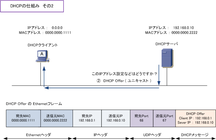
となっているので
--interface=s-veth0って指定してたけど他のネットワーク?のやつに対してはIPアドレス割当できない?
の疑問は s-veth0 からアクセスできるMACアドレスに限定されるという理解で良いのかな?
7章 NAT
NATとは
- Network Address Translationの略
- 特定のプロトコルを指した用語ではない
- 「IPアドレスを変換する」という概念を指す
- 「変換」とはIPアドレスの入ったフィールドを書き換えること
とのこと
一般的なNATの種類
- SNAT(Source NAT)
- DNAT(Destination NAT)
Source NAT
単に
- NAT
- NAPT
というときは多くの場合Source NATを指している
- LAN内のプライベートアドレス -> グローバルアドレスへの書き換えを行うこと
- NATはルーターが担当することが多い
- 送信先: グローバルアドレス
- 送信元: プライベートアドレス
- グローバルアドレスで通信するのでインターネットでルーティングが可能になる
- 戻りのパケットをグローバルアドレス -> プライベートアドレスに変換する処理も行う
- グローバルアドレスとプライベートアドレスを1:Nで扱うためにアドレス+ポート(トランスポート層)の変換が必要になる
- なので実際にはNAPT(Network Address Port Translation)になる
- NAPTにおいてアドレス+ポートの書き換え前と後の対応関係を「セッション」と呼ぶ
TODO: 書き換えを行うポートの範囲などはどうなってるのかと思ったけど↓を見てる限りポート範囲はルーターやその設定次第ということ?
検証環境構築
作るやつ
# NSを作成
$ ip netns add lan
$ ip netns add router
$ ip netns add wan

# 仮想ネットワークインターフェイスを追加
$ ip link add lan-veth0 type veth peer name gw-veth0
$ ip link add wan-veth0 type veth peer name gw-veth1

# 仮想ネットワークインターフェイスをNetwork Namespaceで使えるようにする
$ ip link set lan-veth0 netns lan
$ ip link set gw-veth0 netns router
$ ip link set gw-veth1 netns router
$ ip link set wan-veth0 netns wan

# ネットワークインターフェイスをUP状態にして、利用可能にする
$ ip netns exec lan ip link set lan-veth0 up
$ ip netns exec router ip link set gw-veth0 up
$ ip netns exec router ip link set gw-veth1 up
$ ip netns exec wan ip link set wan-veth0 up

# Routerのアドレスなどを設定
$ ip netns exec router ip addr add 192.0.2.254/24 dev gw-veth0
$ ip netns exec router ip addr add 203.0.113.254/24 dev gw-veth1
$ ip netns exec router sysctl net.ipv4.ip_forward=1

# LANのアドレスなどを設定
$ ip netns exec lan ip addr add 192.0.2.1/24 dev lan-veth0
$ ip netns exec lan ip route add default via 192.0.2.254

# WANのアドレスなどを設定
$ ip netns exec wan ip addr add 203.0.113.1/24 dev wan-veth0
$ ip netns exec wan ip route add default via 203.0.113.254
NATの設定確認
# NATの設定を確認
# iptables = パケットフィルタリング + NATを実装した機能
$ ip netns exec router iptables -t nat -L
Chain PREROUTING (policy ACCEPT)
target     prot opt source               destination

Chain INPUT (policy ACCEPT)
target     prot opt source               destination

Chain POSTROUTING (policy ACCEPT)
target     prot opt source               destination

Chain OUTPUT (policy ACCEPT)
target     prot opt source               destination
NATを設定してみる
以下のコマンドで設定
$ ip netns exec router iptables -t nat \
  -A POSTROUTING \
  -s 192.0.2.0/24 \
  -o gw-veth1 \
  -j MASQUERADE
| オプション | 説明 |
|---|---|
| -A | 処理を追加するチェーンを指定してる |
| -s | 処理対象となる送信元アドレスの範囲 |
| -o | 処理対象とする出力先のネットワークインターフェイス |
| -j | 条件に一致したパケットに対する処理ルールの指定(MASQUERADEはSource NATであることを示す) |
設定内容を確認
$ ip netns exec router iptables -t nat -L
Chain PREROUTING (policy ACCEPT)
target     prot opt source               destination

Chain INPUT (policy ACCEPT)
target     prot opt source               destination

Chain POSTROUTING (policy ACCEPT)
target     prot opt source               destination
MASQUERADE  all  --  192.0.2.0/24         anywhere

Chain OUTPUT (policy ACCEPT)
target     prot opt source               destination
動作確認
別ターミナル1を用意してtcpdumpを実行
$ ip netns exec lan tcpdump -tnel -i lan-veth0 icmp
別ターミナル2を用意してtcpdumpを実行
$ ip netns exec wan tcpdump -tnel -i wan-veth0 icmp
lanからpingを実行
$ ip netns exec lan ping -c 3 203.0.113.1
lan側のtcpdumpの出力結果
$ ip netns exec lan tcpdump -tnel -i lan-veth0 icmp
dropped privs to tcpdump
tcpdump: verbose output suppressed, use -v or -vv for full protocol decode
listening on lan-veth0, link-type EN10MB (Ethernet), capture size 262144 bytes
9a:9b:95:ef:22:a8 > 6e:2b:37:4d:ba:5d, ethertype IPv4 (0x0800), length 98: 192.0.2.1 > 203.0.113.1: ICMP echo request, id 27185, seq 1, length 64
6e:2b:37:4d:ba:5d > 9a:9b:95:ef:22:a8, ethertype IPv4 (0x0800), length 98: 203.0.113.1 > 192.0.2.1: ICMP echo reply, id 27185, seq 1, length 64
9a:9b:95:ef:22:a8 > 6e:2b:37:4d:ba:5d, ethertype IPv4 (0x0800), length 98: 192.0.2.1 > 203.0.113.1: ICMP echo request, id 27185, seq 2, length 64
6e:2b:37:4d:ba:5d > 9a:9b:95:ef:22:a8, ethertype IPv4 (0x0800), length 98: 203.0.113.1 > 192.0.2.1: ICMP echo reply, id 27185, seq 2, length 64
9a:9b:95:ef:22:a8 > 6e:2b:37:4d:ba:5d, ethertype IPv4 (0x0800), length 98: 192.0.2.1 > 203.0.113.1: ICMP echo request, id 27185, seq 3, length 64
6e:2b:37:4d:ba:5d > 9a:9b:95:ef:22:a8, ethertype IPv4 (0x0800), length 98: 203.0.113.1 > 192.0.2.1: ICMP echo reply, id 27185, seq 3, length 64
- 行き:
192.0.2.1 > 203.0.113.1 - 戻り:
203.0.113.1 > 192.0.2.1
となっており共に 192.0.2.1 になっている
wan側のtcpdumpの出力結果
$ ip netns exec wan tcpdump -tnel -i wan-veth0 icmp
dropped privs to tcpdump
tcpdump: verbose output suppressed, use -v or -vv for full protocol decode
listening on wan-veth0, link-type EN10MB (Ethernet), capture size 262144 bytes
9a:3e:44:08:e2:8e > 7e:e4:a9:66:ec:29, ethertype IPv4 (0x0800), length 98: 203.0.113.254 > 203.0.113.1: ICMP echo request, id 27185, seq 1, length 64
7e:e4:a9:66:ec:29 > 9a:3e:44:08:e2:8e, ethertype IPv4 (0x0800), length 98: 203.0.113.1 > 203.0.113.254: ICMP echo reply, id 27185, seq 1, length 64
9a:3e:44:08:e2:8e > 7e:e4:a9:66:ec:29, ethertype IPv4 (0x0800), length 98: 203.0.113.254 > 203.0.113.1: ICMP echo request, id 27185, seq 2, length 64
7e:e4:a9:66:ec:29 > 9a:3e:44:08:e2:8e, ethertype IPv4 (0x0800), length 98: 203.0.113.1 > 203.0.113.254: ICMP echo reply, id 27185, seq 2, length 64
9a:3e:44:08:e2:8e > 7e:e4:a9:66:ec:29, ethertype IPv4 (0x0800), length 98: 203.0.113.254 > 203.0.113.1: ICMP echo request, id 27185, seq 3, length 64
7e:e4:a9:66:ec:29 > 9a:3e:44:08:e2:8e, ethertype IPv4 (0x0800), length 98: 203.0.113.1 > 203.0.113.254: ICMP echo reply, id 27185, seq 3, length 64
- 行き:
203.0.113.254 > 203.0.113.1 - 戻り:
203.0.113.1 > 203.0.113.254
となっておりアドレスが 203.0.113.254 (WANにつながってるrouter側の仮想ネットワークインターフェイス)になっている
例えば4章で同じような構成で試した際には、この構成のlanに相当するns1のtcpdumpは
00:00:5e:00:53:11 > 00:00:5e:00:53:12, ethertype IPv4 (0x0800), length 98: 192.0.2.1 > 198.51.100.1: ICMP echo request, id 65082, seq 1, length 64
00:00:5e:00:53:12 > 00:00:5e:00:53:11, ethertype IPv4 (0x0800), length 98: 198.51.100.1 > 192.0.2.1: ICMP echo reply, id 65082, seq 1, length 64
- 行き:
192.0.2.1 > 198.51.100.1 - 戻り:
198.51.100.1 > 192.0.2.1
となっており、wanに相当するns2のtcpdumpは
> 00:00:5e:00:53:21, ethertype ARP (0x0806), length 42: Reply 198.51.100.1 is-at 00:00:5e:00:53:22, length 28
00:00:5e:00:53:21 > 00:00:5e:00:53:22, ethertype IPv4 (0x0800), length 98: 192.0.2.1 > 198.51.100.1: ICMP echo request, id 65082, seq 1, length 64
00:00:5e:00:53:22 > 00:00:5e:00:53:21, ethertype IPv4 (0x0800), length 98: 198.51.100.1 > 192.0.2.1: ICMP echo reply, id 65082, seq 1, length 64
- 行き:
192.0.2.1 > 198.51.100.1 - 戻り:
198.51.100.1 > 192.0.2.1
とlan側と同様になっている
つまりNATを設定した側では203.0.113.254にアドレスが変換されてるのがわかる
補足
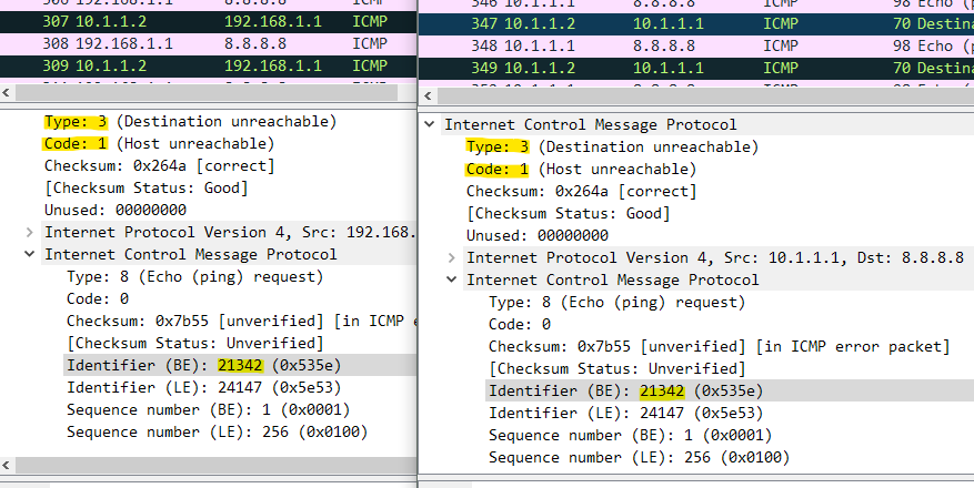
- この検証ではpingを使用したが、pingはICMPというネットワーク層のプロトコルになる
- そのためトランスポート層のポートは存在しない
- ICMPの場合、代わりにエコーリクエスト/エコーリプライのヘッダであるIdentiferというフィールドをポートの代わりに利用することでNAPTを実現しているとのこと
このあたりの詳細は↓の記事で検証込みで解説されていた
Identiferフィールドには↓の画像のように情報が入るらしい
Destination NAT
Destination NATはSource NATとは逆にグローバルアドレス -> プライベートアドレスと変換するやつ
検証環境
検証環境はSource NATで作った環境をそのまま流用
Destination NATを設定
以下のコマンドで設定
$ ip netns exec router iptables -t nat \
  -A PREROUTING \
  -p tcp \
  --dport 54321 \
  -d 203.0.113.254 \
  -j DNAT \
  --to-destination 192.0.2.1
| オプション | 説明 |
|---|---|
| -A | PREROUTINGはインターフェイスからパケットが入って来た直後での処理 |
| -p | 処理対象となるトランスポート層プロトコル |
| --dport | 処理対象となるポート番号 |
| -d | 書き換え前の送信先アドレス(つまりこの例ではグローバルアドレスを想定) |
| -j | 条件に一致した際の処理ルール(DNAT=Destination NAT) |
| --to-destination | 書き換え後の送信先アドレス |
動作確認
lan側でncでサーバー起動する
ncコマンドを使うので入ってなければインストールしておく
$ dnf install nmap-ncat # CentOSなどの場合
以下のコマンドを別ターミナル1で実行
$ ip netns exec lan nc -lnv 54321
wan側から接続する
以下のコマンドを別ターミナル2で実行
$ ip netns exec wan nc 203.0.113.254 54321
上記を実行するとサーバー側で以下のような出力が出てくる
$ ip netns exec lan nc -lnv 54321
Ncat: Version 7.70 ( https://nmap.org/ncat )
Ncat: Listening on :::54321
Ncat: Listening on 0.0.0.0:54321
Ncat: Connection from 203.0.113.1.
Ncat: Connection from 203.0.113.1:51936.
tcpdumpでパケットキャプチャを行う
更に別のターミナルで以下のコマンドを実行してキャプチャする
$ ip netns exec wan tcpdump -tnl -i wan-veth0 "tcp and port 54321"
もう1つのターミナルでlan側もキャプチャ
$ ip netns exec lan tcpdump -tnl -i lan-veth0 "tcp and port 54321"
クライアント側でメッセージ送信
ncで接続してるクライアントから↓のようにメッセージを送る
$ ip netns exec wan nc 203.0.113.254 54321
Hello World! # <- 適当な文字を入力してEnter
送るとサーバー側では↓のように送信したメッセージが表示される
$ ip netns exec lan nc -lnv 54321
Ncat: Version 7.70 ( https://nmap.org/ncat )
Ncat: Listening on :::54321
Ncat: Listening on 0.0.0.0:54321
Ncat: Connection from 203.0.113.1.
Ncat: Connection from 203.0.113.1:51936.
Hello World! # <- これ
wan: tcpdump側の結果確認
$ ip netns exec wan tcpdump -tnl -i wan-veth0 "tcp and port 54321"
dropped privs to tcpdump
tcpdump: verbose output suppressed, use -v or -vv for full protocol decode
listening on wan-veth0, link-type EN10MB (Ethernet), capture size 262144 bytes
IP 203.0.113.1.51936 > 203.0.113.254.54321: Flags [P.], seq 3676815547:3676815560, ack 847630801, win 229, options [nop,nop,TS val 1158625922 ecr 2850883683], length 13
IP 203.0.113.254.54321 > 203.0.113.1.51936: Flags [.], ack 13, win 227, options [nop,nop,TS val 2851086939 ecr 1158625922], length 0
- 行き:
203.0.113.1.51936 > 203.0.113.254.54321 - 帰り:
203.0.113.254.54321 > 203.0.113.1.51936
となってるのがわかる
lan: tcpdump側の結果確認
$ ip netns exec lan tcpdump -tnl -i lan-veth0 "tcp and port 54321"
dropped privs to tcpdump
tcpdump: verbose output suppressed, use -v or -vv for full protocol decode
listening on lan-veth0, link-type EN10MB (Ethernet), capture size 262144 bytes
IP 203.0.113.1.51936 > 192.0.2.1.54321: Flags [P.], seq 3676815560:3676815573, ack 847630801, win 229, options [nop,nop,TS val 1158835120 ecr 2851086939], length 13
IP 192.0.2.1.54321 > 203.0.113.1.51936: Flags [.], ack 13, win 227, options [nop,nop,TS val 2851296137 ecr 1158835120], length 0
- 行き:
203.0.113.1.51936 > 192.0.2.1.54321 - 帰り:
192.0.2.1.54321 > 203.0.113.1.51936
のようになっておりアドレスが 203.0.113.254.54321(ルータのWAN側のネットワークインターフェイス) -> 192.0.2.1.54321(DNAT先のLANのインターフェイス) に変換されているのがわかる