Closed8
PICマイコン頑張る
PICマイコン 書き込み用のデバッガ
IDEとかのインストールはここから これ見ながら進める
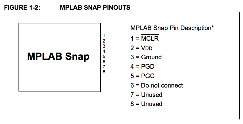
snapのピン配列
Configuration Bitsの設定
参考: http://zattouka.net/GarageHouse/micon/MPLAB/16F1938/SWtoLED/SWtoLED.htm
// CONFIG1
#pragma config FOSC = HS        // Oscillator Selection (HS Oscillator, High-speed crystal/resonator connected between OSC1 and OSC2 pins)
#pragma config WDTE = OFF       // Watchdog Timer Enable (WDT disabled)
#pragma config PWRTE = ON       // Power-up Timer Enable (PWRT enabled)
#pragma config MCLRE = OFF      // MCLR Pin Function Select (MCLR/VPP pin function is digital input)
#pragma config CP = OFF         // Flash Program Memory Code Protection (Program memory code protection is disabled)
#pragma config CPD = OFF        // Data Memory Code Protection (Data memory code protection is disabled)
#pragma config BOREN = ON       // Brown-out Reset Enable (Brown-out Reset enabled)
#pragma config CLKOUTEN = OFF   // Clock Out Enable (CLKOUT function is disabled. I/O or oscillator function on the CLKOUT pin)
#pragma config IESO = OFF       // Internal/External Switchover (Internal/External Switchover mode is disabled)
#pragma config FCMEN = ON       // Fail-Safe Clock Monitor Enable (Fail-Safe Clock Monitor is enabled)

// CONFIG2
#pragma config WRT = OFF        // Flash Memory Self-Write Protection (Write protection off)
#pragma config VCAPEN = OFF     // Voltage Regulator Capacitor Enable (All VCAP pin functionality is disabled)
#pragma config PLLEN = ON       // PLL Enable (4x PLL enabled)
#pragma config STVREN = ON      // Stack Overflow/Underflow Reset Enable (Stack Overflow or Underflow will cause a Reset)
#pragma config BORV = HI        // Brown-out Reset Voltage Selection (Brown-out Reset Voltage (Vbor), high trip point selected.)
#pragma config LVP = ON         // Low-Voltage Programming Enable (Low-voltage programming enabled)
DEBUGの項目はあると怒られるので、設定した後に消す
ミスって取り返しがつかなくなった
どうすることも出来なさそう
マイコン買いなおしてみる
安いやつ
RA2ピンでLチカしたいので、こんな感じにする
#pragma config FOSC = INTOSC    // Oscillator Selection bits (EC: CLKIN function enabled)
#pragma config BOREN = ON       // Brown-out Reset Enable (Brown-out Reset enabled)
#pragma config WDTE = OFF       // Watchdog Timer Enable (WDT disabled)
#pragma config PWRTE = ON       // Power-up Timer Enable bit (PWRT enabled)
#pragma config MCLRE = OFF      // MCLR Pin Function Select bit (MCLR pin function is digital input, MCLR internally tied to VDD)
#pragma config CP = OFF         // Code Protection bit (Program memory code protection is disabled)
#pragma config LVP = ON         // Low-Voltage Programming Enable (Low-voltage programming enabled)
#pragma config LPBOR = ON       // Brown-out Reset Selection bits (BOR enabled)
#pragma config BORV = LO        // Brown-out Reset Voltage Selection (Brown-out Reset Voltage (Vbor), low trip point selected.)
#pragma config WRT = OFF        // Flash Memory Self-Write Protection (Write protection off)

#include <xc.h>

#define _XTAL_FREQ 1000000

void main(void)
{
	TRISA2 = 0;	// Set output
	ANSELA = 0;
	RA2 = 1;	// Set High
	while(1)
	{
		RA2 ^= 1;	// Toggle
		__delay_ms(1000);
	}

	//return;
}
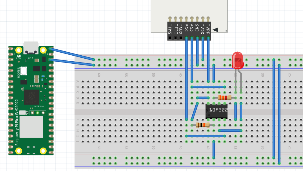
書き込みの回路図はこれを参考にする

このスクラップは2ヶ月前にクローズされました