Virtio memo

(上記論文から引用)
Virtioは仮想環境内で最適化されたデバイスI/O操作をするための準仮想化フレームワーク。
ホストOSとゲストOSの間で共有されたメモリ上にキューを置き、そのキューを利用してデータの入出力を行う。このキューのことをvirtqueuesと呼ぶ。
 lspci
05ee:00:00.0 SCSI storage controller: Red Hat, Inc. Virtio console (rev 01)
07a7:00:00.0 System peripheral: Red Hat, Inc. Virtio file system (rev 01)
fd77:00:00.0 3D controller: Microsoft Corporation Device 008e
ワイのwsl環境にもしっかりvirtioデバイスがいた
ちなみに準仮想化は、ゲストOSが物理ハードウェアへのアクセスを仮想化レイヤを介して行うのではなく、最適化されたインターフェースを通してアクセスすることで、オーバーヘッドを削減しパフォーマンス向上を実現するためのもの。
ここでいう「最適化されたインターフェース」とは、Virtioにおけるvirtqueuesのことを指す。(正確にはVirtio自体がインターフェースだと思うけど)
準仮想化ドライバーはゲストのパフォーマンスを向上し、ゲスト I/O レイテンシーを下げ、ベアメタルレベルまでスループットを増加させます。I/O の高いタスクとアプリケーションを実行する完全に仮想化されたゲストには、準仮想化ドライバーを使用することが推奨されます。
Virtioを用いた準仮想化デバイスドライバの一例として、virtio_netがある。
これは、Virtioの上に構築されたネットワークデバイスのドライバである。
virtio_netを用いたパケット送信の大まかな流れ
- ゲストOSのデバイスドライバから、virtqueuesにパケットを送信する
- KVMに制御が移る
- KVMがqemu(Virtioのバックエンドを担う)のタスクをスケジューリングする
- Virtioのバックエンドがvirtqueuesからパケットを取得し、I/Oのエミュレートをする
完全仮想化は、エミュレートされたデバイスを通してゲストOSとハイパーバイザの通信を行う。
それに対して準仮想化は、ゲストOSとハイパーバイザ間で直接やり取りを行うからエミュレーションステップがいらない。だから準仮想化のほうがパフォーマンスが良い。
kvmとqemuの役割の違いがちゃんとまだ分かってないな
qemuの引数にkvmを使うかどうかの引数があった
-enable-kvm
仮想化について
仮想化は一つのコンピューターリソースを分割して複数に見せたり、複数のコンピューターリソースを一つに見せたりするような技術。仮想マシン上でosを動かせるような環境をシステム仮想マシンと言ったりする。
完全仮想化
完全仮想化はハードウェア環境をソフトウェアで完全に再現することによって、ゲストOSに手を加えることなくそのまま仮想環境に乗せることができる。ゲストOSは疑似的なハードウェア環境を物理ハードウェア環境と勘違いして動作をする。
利点
ゲストOSに手を加えなくてもそのまま動かせる。(互換性がある)
欠点
ハイパーバイザとゲストOSのやり取りが、エミュレートされたハードウェアデバイスを介して行われるため、いちいちエミュレートしたデバイスを経由してそれをハイパーバイザが解釈する必要がある。これによってパフォーマンスのオーバーヘッドが大きくなる。
準仮想化
準仮想化は、ゲストOSが仮想環境で動くことを前提とし、ゲストOSとハイパーバイザが独自の通信方法で直接やり取りを行う仮想化技術。
利点
ハイパーバイザとゲストOSのやり取りにエミュレートされたハードウェアデバイスを挟まないので、オーバーヘッドの削減が見込める。
欠点
互換性がない。仮想環境でしか動かない。
なんとなくkvmとqemuの動作がつかめてきた
Linux KVMについて
KVM(Kernel-based Virtual Machine)はLinuxカーネルを仮想マシンの実行環境(要するにハイパーバイザ)として提供するためのカーネルモジュールである。これはカーネルモジュールなのでOSのメモリ管理やプロセススケジューリングなどを積極的に活用して、効率的な仮想化環境を提供できる。
KVMはCPUの仮想化支援機能を用いて仮想マシンを作ることができる。この仮想マシンには仮想CPUが搭載されている。通常、ソフトウェアでエミュレートしたCPUを使うと、実際のCPUで一つの命令で済む場合でも、何十もの命令に置き換えられてしまう(エミュレートして実際のCPUが実行するから)ので、性能が著しく低下する。
しかし仮想化支援機能によって、仮想マシン内の命令実行がホストマシンの物理CPUに直接移譲され命令が実行される。
すなわち、KVMを使う最大の利点はCPUの仮想化支援技術を利用して、効率的な命令実行ができることにある。
QEMUについて
QEMUは仮想マシンソフトウェア(ユーザーアプリ)であり、CPU、メモリ、I/Oデバイスなどのハードウェアコンポーネントをエミュレートすることができる。
普段のOS開発でお世話になってるやつ。これ単体で仮想マシンとして動かすことはできるが、先ほど述べたようにソフトウェアでエミュレートしたCPUはとても効率が悪い。
どのように協調するのか
KVMによって仮想CPUを提供し、QEMUによってメモリやI/Oデバイスを提供するようにすることで、CPUの仮想化支援技術を用いてCPUの命令を効率よく実行しつつ、QEMUによってエミュレートされたメモリやI/Oデバイスを使用できる。

雑なイメージ
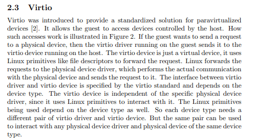
- ゲストOSの準仮想化(Virtio)デバイスドライバがVirtio queuesにパケットを送信する。
- 送信後にデバイスドライバがKVM(ハイパーバイザ)に処理を渡す(ここでVMExitが発生)
- KVMはQEMUのタスクをスケジューリングする
- QEMUは、Virtio queuesからメッセージを受け取りI/Oデバイス(ネットワークデバイス)のエミュレートをして、Virtio queuesにパケットを送ったり送らなかったりする
- ゲストOSに制御が戻り、Virtio queuesに格納されているデータを処理する
Intel VT-xについて
プロセッサが、仮想マシンの実行からハイパーバイザの実行に切り替わることをVMExitという。
このVMExitは、仮想マシンの実行におけるオーバーヘッドになる。
完全仮想化のデバイスが遅い理由はここにあり、エミュレートされたデバイスのハードウェアレジスタに対するアクセスが検知されるたびにVMExitが走るらしい。
準仮想化デバイスの場合、ゲストOSがキューにメッセージを送ってKVMにトラップするときぐらいしか使われないみたい。VMExitの抑制になるから結果的に早くなるのかな。
Virtioは準仮想化デバイスとはいえ、ハイパーバイザ上でなければ実現できないような挙動には依存しない。
virtioの仕様書結構見やすくてありがたい
ドライバがデバイスを初期化する流れ
- Reset the device.
- Set the ACKNOWLEDGE status bit: the guest OS has noticed the device.
- Set the DRIVER status bit: the guest OS knows how to drive the device.
- Read device feature bits, and write the subset of feature bits understood by the OS and driver to the device. During this step the driver MAY read (but MUST NOT write) the device-specific configuration fields to check that it can support the device before accepting it.
- Set the FEATURES_OK status bit. The driver MUST NOT accept new feature bits after this step.
- Re-read device status to ensure the FEATURES_OK bit is still set: otherwise, the device does not support our subset of features and the device is unusable.
- Perform device-specific setup, including discovery of virtqueues for the device, optional per-bus setup, reading and possibly writing the device’s virtio configuration space, and population of virtqueues.
- Set the DRIVER_OK status bit. At this point the device is “live”.
それぞれのstatus
ACKNOWLEDGE (1)
Indicates that the guest OS has found the device and recognized it as a valid virtio device.
DRIVER (2)
Indicates that the guest OS knows how to drive the device. Note: There could be a significant (or infinite) delay before setting this bit. For example, under Linux, drivers can be loadable modules.
FAILED (128)
Indicates that something went wrong in the guest, and it has given up on the device. This could be an internal error, or the driver didn’t like the device for some reason, or even a fatal error during device operation.
FEATURES_OK (8)
Indicates that the driver has acknowledged all the features it understands, and feature negotiation is complete.
DRIVER_OK (4)
Indicates that the driver is set up and ready to drive the device.
DEVICE_NEEDS_RESET (64)
Indicates that the device has experienced an error from which it can’t recover.
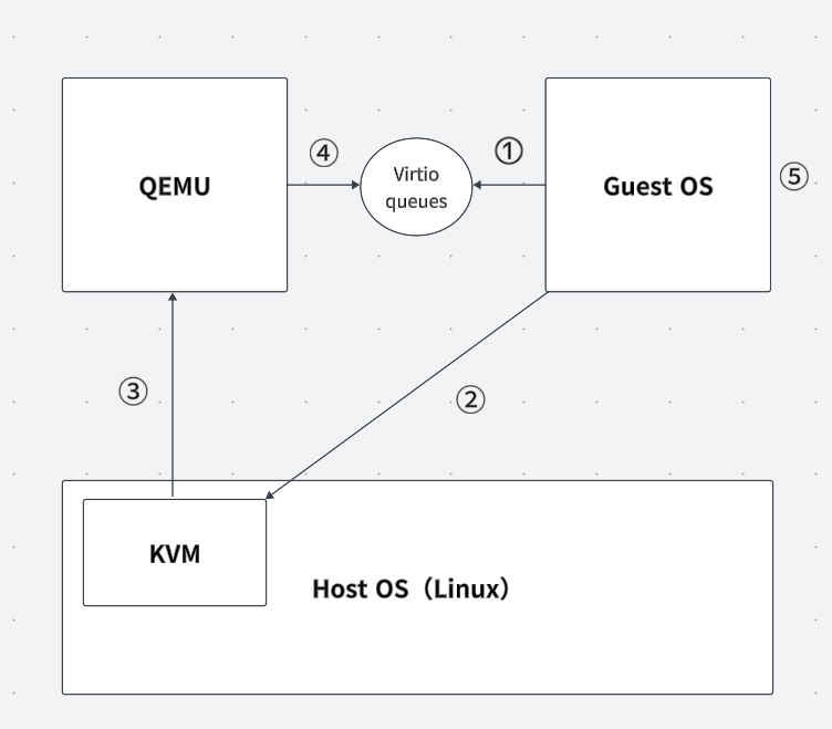
とりあえず検出したpciデバイス表示させたいから先にlspsiを実装する
VirtIOデバイスをQEMUに追加する場合、それぞれのデバイスに対応するディスクイメージが必要
これでvirtio-blkが認識されるようになった
qemu-system-x86_64 -m 1G \
    -drive if=pflash,format=raw,file=OVMF_CODE.fd \
    -drive if=pflash,format=raw,file=OVMF_VARS.fd \
    -drive if=ide,index=0,media=disk,format=raw,file=$disk_img \
    -device nec-usb-xhci,id=xhci \
    -device usb-kbd \
    -drive if=none,id=drive-virtio-disk0,format=raw,file=$storage_img \
    -device virtio-blk-pci,drive=drive-virtio-disk0,id=virtio-disk0 \
    -monitor stdio -S -gdb tcp::12345

雑に出力した
ベンダーIDが1AF4のベンダーはRed Hatであり、そのデバイスIDが1なのでVirtio block deviceが識別されていることがわかる。
lspciコマンドを雑に作った。検出できていないデバイス2個あるけどVirtioの実装一通り終わったら直そう
Virtioで定義されている整数データ型
u8, u16, u32, u64 : 符号なし整数
le16, le32, le64 : リトルエンディアンの符号なし整数
be16, be32, be64 : ビッグエンディアンの符号なし整数
Virtqueuesについて
The mechanism for bulk data transport on virtio devices is pretentiously called a virtqueue. Each device can have zero or more virtqueues.
Driver makes requests available to device by adding an available buffer to the queue, i.e., adding a buffer describing the request to a virtqueue, and optionally triggering a driver event, i.e., sending an available buffer notification to the device.
Device executes the requests and - when complete - adds a used buffer to the queue, i.e., lets the driver know by marking the buffer as used. Device can then trigger a device event, i.e., send a used buffer notification to the driver.
Device reports the number of bytes it has written to memory for each buffer it uses. This is referred to as “used length”.
Device is not generally required to use buffers in the same order in which they have been made available by the driver.
Some devices always use descriptors in the same order in which they have been made available. These devices can offer the VIRTIO_F_IN_ORDER feature. If negotiated, this knowledge might allow optimizations or simplify driver and/or device code.
バージョン2.7以前の名称 → 現在の名称
- Descriptor Table → Descriptor Area
- Available Ring → Driver Area
- Used Ring → Device Area
まずはvirtioデバイスの初期化処理から作るか。 このあたりからVirtio Over PCI Bus を使用する Virtio デバイスの仕様が書かれている
VirtioのPCIデバイスレイアウト
設定方法
- I/O領域やメモリ領域を介して、デバイスの設定が行われる。これらの領域は、Virtio Structure PCI Capabilitiesによって指定される。
- デバイス構成内のすべてのフィールドはリトルエンディアン。
- 64ビットフィールドは、二つの32ビットフィールドとして扱われる。
ドライバがアクセスするには
- 8ビットフィールドに対して、8ビット幅のアクセス。
- 16ビットフィールドには、16ビット幅でアラインしてアクセス。
- 32ビットおよび64ビットのフィールドに対しては、32ビット幅でアラインされたアクセス。
- 64ビットのフィールドは、ドライバが高い32ビット部分と低い32ビット部分をそれぞれ独立してアクセスできる。
Virtio Structure PCI Capabilities
Virtio Structure PCI Capabilitiesは、VirtioのPCIデバイスにおけるPCI Capabilitiesの領域を指す。
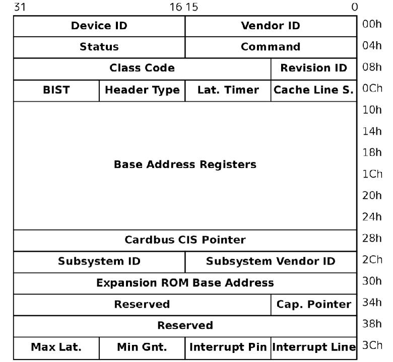
PCI CapabilitiesはPCIコンフィギュレーション空間における拡張領域。0x00から0x3FはPCIデバイス共通の設定が含まれており、0x40以降が拡張領域(これがPCI Capabilities)となる。
Virtioデバイスのコンフィギュレーションレイアウトは以下の構造体たちで構成されている。
- Common configuration
- Notifications
- ISR Status
- Device-specific configuration (optional)
- PCI configuration access
これらの構造体は、BAR(Base Address Register)か VIRTIO_PCI_CAP_PCI_CFGというPCIコンフィギュレーション空間内の特別なフィールドからアクセスできる。
struct virtio_pci_cap {
        u8 cap_vndr;    /* Generic PCI field: PCI_CAP_ID_VNDR */
        u8 cap_next;    /* Generic PCI field: next ptr. */
        u8 cap_len;     /* Generic PCI field: capability length */
        u8 cfg_type;    /* Identifies the structure. */
        u8 bar;         /* Where to find it. */
        u8 id;          /* Multiple capabilities of the same type */
        u8 padding[2];  /* Pad to full dword. */
        le32 offset;    /* Offset within bar. */
        le32 length;    /* Length of the structure, in bytes. */
};
PCI Capabilitiesに格納されているvirtio_pci_capのbar&offsetから該当のbarとそのオフセットを見つける→ barの特定オフセットにcfg_typeに応じた構造体が格納されている。
PCI Capabilitiesからvirtio_pci_cap を探すときは、cap_nextを走査するイメージ。
Common configuration
struct virtio_pci_common_cfg {
        /* About the whole device. */
        le32 device_feature_select;     /* read-write */
        le32 device_feature;            /* read-only for driver */
        le32 driver_feature_select;     /* read-write */
        le32 driver_feature;            /* read-write */
        le16 config_msix_vector;        /* read-write */
        le16 num_queues;                /* read-only for driver */
        u8 device_status;               /* read-write */
        u8 config_generation;           /* read-only for driver */

        /* About a specific virtqueue. */
        le16 queue_select;              /* read-write */
        le16 queue_size;                /* read-write */
        le16 queue_msix_vector;         /* read-write */
        le16 queue_enable;              /* read-write */
        le16 queue_notify_off;          /* read-only for driver */
        le64 queue_desc;                /* read-write */
        le64 queue_driver;              /* read-write */
        le64 queue_device;              /* read-write */
        le16 queue_notify_data;         /* read-only for driver */
        le16 queue_reset;               /* read-write */
};
ドライバは以下のフィールドに書き込んではいけない。
- device_feature
- num_queues
- config_generation
- queue_notify_off
- queue_notify_data
queue_enable で virtqueue を有効にする前に、他の virtqueue フィールドを設定しなければならない。
device_status に 0 を書き込んだ後、ドライバはデバイスを再初期化する前に device_status の読み込みが 0 を返すのを待たなければならない。
ドライバは queue_enable に 0 を書き込んではいけない。
Notifications
Notificationsは、VIRTIO_PCI_CAP_NOTIFY_CFGを使用して見つける必要がある。
struct virtio_pci_notify_cap {
        struct virtio_pci_cap cap;
        le32 notify_off_multiplier; /* Multiplier for queue_notify_off. */
};
virtqueue の BAR 内のキュー通知アドレスの求め方
cap.offset + queue_notify_off * notify_off_multiplier
ISR status
Virtio PCIデバイスにおいて割り込みステータスを管理するための特定の機能を提供する。このCapabilityにより提供されるISR(Interrupt Status Register)は、ドライバがデバイスからの割り込みを適切に処理するのに必要な情報を提供する。
PCIコンフィギュレーション空間内の特定のオフセットに配置される。このオフセットは、virtio_pci_cap 構造体の offset フィールドを通じて特定される。この構造体はbar フィールドによって指定されたBARを介してアクセスされる場合が多い。
ISRの構造
| Bits | 0 | 1 | 2 to 31 |
|---|---|---|---|
| Purpose | Queue Interrupt | Device Configuration Interrupt | Reserved |
ドライバが割り込みを受信したときにどこからの割り込みかを判断するためにISRステータスレジスタを読みだす感じか。
Virtio Structure PCI Capabilitiesはだいぶ理解が深まった
MSIとMSI-Xの違いをちゃんと理解していない(拡張版ってことしか知らん)
virtioの仕様としてサポートしているのがINTxとMSI-X。
仕様書にMSIの言及は特になし。
If MSI-X capability is disabled:
Read the ISR Status field, which will reset it to zero.
If the lower bit is set: look through all virtqueues for the device, to see if any progress has been made by the device which requires servicing.
If the second lower bit is set: re-examine the configuration space to see what changed.
If MSI-X capability is enabled:
Look through all virtqueues mapped to that MSI-X vector for the device, to see if any progress has been made by the device which requires servicing.
If the MSI-X vector is equal to config_msix_vector, re-examine the configuration space to see what changed.
あ、でも上記の仕様書の記載からMSIも使えそうな雰囲気が感じ取れる。
やっぱむりっぽい。MSI-Xの対応しなきゃかあ...めんどい
MSIについて
Trigger Mode
割り込み信号がどのように発生するかを定義する。
- Edge Triggered : 割り込み信号のエッジ(信号の変化)が割り込みを発生させる。信号が低から高に変わる瞬間(立ち上がりエッジ)や、高から低に変わる瞬間(立ち下がりエッジ)に割り込みがトリガーされる。
- Level Triggered : 割り込み信号のレベル(信号の状態)が割り込みを発生させる。信号が特定のレベル(高か低)に保持されている間割り込みがアクティブになる。
Delivery Mode
CPUに割り込みがどのように配信されるかを指定する。
- Fixed : 固定配信モード。指定された特定のCPUコアに対して割り込みを配送する。このモードを使用することが一般的。
- Lowest Priority : 最低優先度配信モード。MSIでは使わない。
- SMI, NMI, INIT, ExtINT : MSIでは使わない。
MSI
Capability

- Message AddressとMessage Dataは、Header部分の直後に配置されている。
MSI-X
Capability

- Message AddressとMessage Dataは、BARで指定されるMMIO領域に配置されている。
MSI-X Table

各割り込みについての詳細設定を格納するテーブル。
- Vector Control : 割り込みのコントロールオプション。割り込みのマスクとかも含まれていて個別の割り込みを動的に無効/有効にすることができる。
- Message Data : 割り込みに関連するデータ(割り込みベクタとか)が含まれる。
- Message Address : 割り込みが送信されるプロセッサのローカルAPICのアドレスなどを指定する。
MSI-X PBA Table
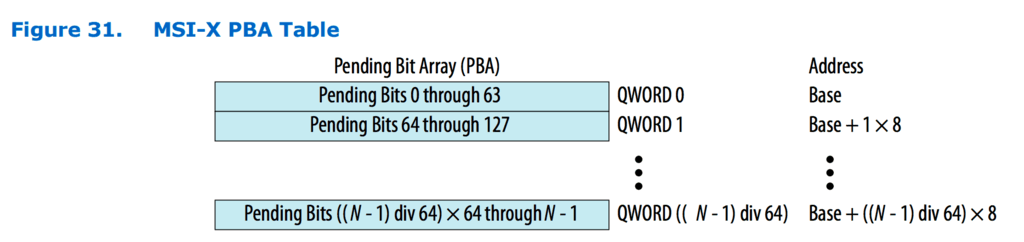
MSI-X PBA(Pending Bit Array) Tableはアクティブながらまだ処理されてない割り込みを追跡するためのテーブル。
ドライバや割り込みハンドラが割り込みを効率的に処理するために、どの割り込みがペンディング状態にあるかをすぐに確認できる。
共通している構造
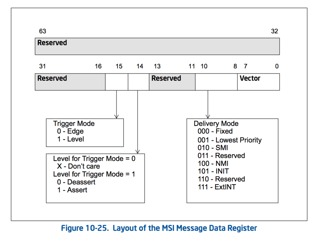
Message Address Register
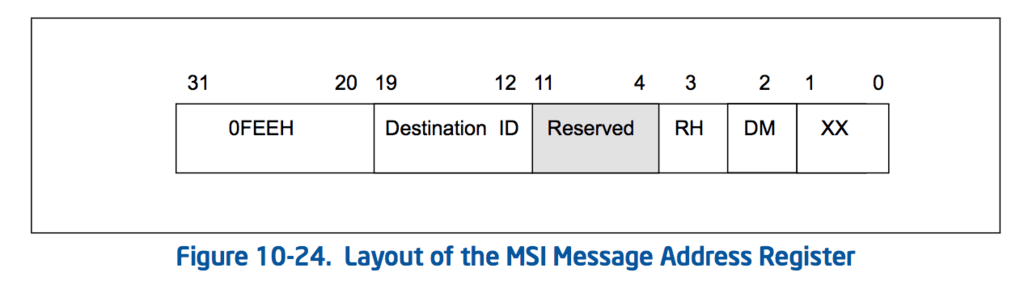
Message Data Register
大まかなMSI-Xの設定手順
- PCIデバイスを検出する
- Capability Pointerの取得
- MSI-X Capabilityの探索
- MSI-X Capabilityエントリから、MSI-X TableとPBA Tableのアドレス取得
- MSI-X Tableの設定
- 割り込みの有効化
って感じか。意外とそこまで複雑ではなさそうだった

MSI-X Tableの格納されているBARとそのオフセットを取れた
PBA TableのほうはBARとオフセットともにゼロだった。これは、virtio_blkでは使わないということかな?
msi_x_capabilityの設定コード書いてみた。動くかな。
void write_msi_x_capability(const device& dev,
                            const msi_x_capability& msix_cap,
                            uint64_t msg_addr,
                            uint32_t msg_data)
{
	uint64_t table_bar = read_base_address_register(dev, msix_cap.table_bar);

	auto* msix_table =
			reinterpret_cast<msix_table_entry*>(table_bar + msix_cap.table_offset);

	msix_table->msg_addr = msg_addr & 0xffffffffU;
	msix_table->msg_upper_addr = msg_addr >> 32;
	msix_table->msg_data = msg_data;

	// Memory barrier to ensure writes are not reordered
	asm volatile("mfence" ::: "memory");
}
MSI-Xうまく動かないな...
BARのオフセットとインデックスの取得方法を間違えている可能性がある
見逃している設定があった。
The maximum table size is 2048 entries. Each 16-byte entry is divided in 4 fields as shown in the figure below. The MSI-X table can be accessed on any BAR configured. The base address of the MSI-X table must be aligned to a 4 KB boundary.
どうやらMSI-X tableのアドレスは4KiB境界アラインする必要があるらしい。
長らく詰まっていたMSI-Xようやく機能した...
動かなかった原因
Specifies the memory address offset for the MSI-X Table relative to the BAR base address value of the BAR number specified in MSI-X Table BAR Indicator,[2:0] above. The address is extended by appending 3 zeros to create quad-word alignment.
オフセットを8バイト境界にアラインするために、左に3ビットシフトする必要があった。
uint64_t bar_addr = read_base_address_register(dev, msix_cap.table.bits.bar);
bar_addr &= 0xffff'ffff'ffff'f000U;
bar_addr += msix_cap.table.bits.offset << 3;
auto* table_entry = reinterpret_cast<msix_table_entry*>(bar_addr);
barのアドレスを4KIBアラインしたものと、オフセットを3bit左にシフトしたものを足すことで、MSI-X Tableのアドレスを得ることができた。もっとしっかり仕様書読むべきだったと反省。
Virtio Structure PCI Capabilitiesはどこから取れるんだろうか。
PCIコンフィグレーション空間
0x34オフセットからcapability listを走査する。

走査してみた。cap_idが9のものがvirtioのcapability。ちなみに17(0x11)はMSI-X用のCapabilityである。
Capability読み込んでみたけどbar以降がちゃんと読み込めてない気がする
PCI Configuration AccessのCap(config_type 5)だけが正しく取得できていない

問題なかった。仕様書見返したらPCI Configuration AccessのCapに至ってはそういう仕様だった。
The VIRTIO_PCI_CAP_PCI_CFG capability creates an alternative (and likely suboptimal) access method to the common configuration, notification, ISR and device-specific configuration regions.
The capability is immediately followed by an additional field like so:
struct virtio_pci_cfg_cap {
        struct virtio_pci_cap cap;
        u8 pci_cfg_data[4]; /* Data for BAR access. */
};
The fields cap.bar, cap.length, cap.offset and pci_cfg_data are read-write (RW) for the driver.
To access a device region, the driver writes into the capability structure (ie. within the PCI configuration space) as follows:
The driver sets the BAR to access by writing to cap.bar.
The driver sets the size of the access by writing 1, 2 or 4 to cap.length.
The driver sets the offset within the BAR by writing to cap.offset.
At that point, pci_cfg_data will provide a window of size cap.length into the given cap.bar at offset cap.offset.
↑ これを要約すると
VIRTIO_PCI_CAP_PCI_CFGのケイパビリティはvirtio_pci_capを拡張した以下のような構造になっている。
struct virtio_pci_cfg_cap {
struct virtio_pci_cap cap;
u8 pci_cfg_data[4]; /* Data for BAR access. */
};
それぞれのフィールド
- cap.bar : デバイスのアクセスしたいBARインデックスを書き込む。
- cap.length : アクセスするデータのサイズを決める。1~4 byte。
- cap.offset : BAR内でアクセスするデータの開始位置。
- pci_cfg_data : 上の三つの設定が終わった後にこのフィールドにアクセスすると指定した位置の読み書きが可能なデータウィンドウとして機能する。
他のVirtio Structure PCI Capabilitiesの構造体はのbarやlength,offsetなのは読み取り専用なのに対して、VIRTIO_PCI_CAP_PCI_CFGにおいては書き込み用のフィールドになる。
自分のosではvirtio_pci_capを以下のように定義することにした。
struct virtio_pci_cap {
	union {
		uint32_t data;

		struct {
			uint8_t cap_vndr; /* Generic PCI field: PCI_CAP_ID_VNDR */
			uint8_t cap_next; /* Generic PCI field: next ptr. */
			uint8_t cap_len;  /* Generic PCI field: capability length */
			uint8_t cfg_type; /* Identifies the structure. */
		} __attribute__((packed)) fields;
	} first_dword;

	union {
		uint32_t data;

		struct {
			uint8_t bar;		/* Where to find it. */
			uint8_t id;			/* Multiple capabilities of the same type */
			uint8_t padding[2]; /* Pad to full dword. */
		} __attribute__((packed)) fields;
	} second_dword;

	uint32_t offset; /* Offset within bar. */
	uint32_t length; /* Length of the structure, in bytes. */

	virtio_pci_cap* next;
} __attribute__((packed));
ロードしやすいようにunionでまとめて、アクセスしやすいように数珠つなぎにした。
登録されてるcapabilityを全て検出することができた。

次は、それぞれのcapabilityに設定を登録していく必要がある。
- Common configuration
- Notifications
- ISR Status
- Device-specific configuration (optional)
- PCI configuration access
このうち、Common configuration、Notifications、ISR Statusは設定が必須
とりあえずこのまま初期化進めてみる。
virtio_blk関連のfeature_bit
- VIRTIO_BLK_F_SIZE_MAX: 最大セグメントサイズを制限する。
- VIRTIO_BLK_F_SEG_MAX: セグメントの最大数を制限する。
- VIRTIO_BLK_F_GEOMETRY: ディスクのジオメトリ(CHS)を提供する。
- VIRTIO_BLK_F_RO: リードオンリー操作。
- VIRTIO_BLK_F_BLK_SIZE: ブロックサイズを報告する。
- VIRTIO_BLK_F_FLUSH: フラッシュコマンドをサポートする。
- VIRTIO_BLK_F_TOPOLOGY: トポロジ情報(物理ブロックのサイズなど)を提供する。
- VIRTIO_BLK_F_CONFIG_WCE: 書き込みキャッシュを有効/無効にする。
Virtioの仕組みでは、driver_featureにドライバがセットした機能ビットがデバイスによって認識され、その結果としてドライバはその機能を使用できるようになる。このプロセスは機能ネゴシエーションと呼ばれ、デバイスとドライバ間でサポートされる機能を合意する。拡張機能的な感じだね。
ドライバのデバイス初期化手順
-
デバイスのリセット
デバイスの状態を初期状態に戻すために、device_status レジスタに 0 を書き込む。device_statusに0を書き込んだ後、ドライバはデバイスを再初期化する前にdevice_statusの読み出しが0を返すのを待たなければならない。 -
ACKNOWLEDGE ステータスビットの設定
ゲストOSがデバイスを認識したことを示すために、device_status レジスタに 1 (ACKNOWLEDGE) を設定する。 -
DRIVER ステータスビットの設定
ゲストOSがデバイスを操作する方法を知っていることを示すために、device_status レジスタに 2 (DRIVER) を追加する。 -
デバイス機能ビットの読み取りと設定
デバイスが提供する機能ビットを device_feature レジスタから読み取り、ドライバがサポートする機能のサブセットを driver_feature レジスタに書き込む。
このステップでは、デバイス固有の設定フィールドを読むことができるが、書き込みはできない。 -
FEATURES_OK ステータスビットの設定
サポートする機能ビットがデバイスに正しく設定されたことを確認した後、device_status レジスタに 8 (FEATURES_OK) を追加します。
このビットを設定した後は、新しい機能ビットを受け入れてはならない。 -
device_status の再確認
FEATURES_OK ビットが設定された状態で device_status レジスタを再度読み取り、確認する。もしビットがクリアされていれば、デバイスはサポートされている機能のサブセットをサポートしていないことになり、デバイスは使用不可。 -
デバイス固有の設定
デバイスのvirtqueuesを発見し、バス固有の設定を行い、必要に応じてデバイスのVirtio設定スペースを読み書きする。また、virtqueuesを準備する。 -
DRIVER_OK ステータスビットの設定
デバイスが「ライブ」状態になることを示すために、device_status レジスタに 4 (DRIVER_OK) を追加。
msix_config
デバイス全体に対する設定変更を通知するための MSI-X ベクタを指定する。これは、デバイスの全体的な設定が変更されたときに割り込みを生成するために使用される。例えば、デバイスのリセットや特定の設定パラメータの変更などがこのベクタを通じてホストに通知される。
queue_msix_vector
特定の virtqueue に関連するイベントのための MSI-X ベクタを指定する。これは、データの送受信やキューの状態変更など、特定の virtqueue に限定された操作に関連する割り込みを生成するために使用される。
デバイスに依存しないフィーチャービット
-
VIRTIO_F_INDIRECT_DESC (28):
ドライバが間接ディスクリプタを使用できることを示す。これにより、単一のディスクリプタから複数のディスクリプタを参照することが可能になり、データ構造の柔軟性が向上する。 -
VIRTIO_F_EVENT_IDX (29):
used_event と avail_event フィールドを使用することを可能にし、効率的なイベント通知が実現する。 -
VIRTIO_F_VERSION_1 (32):
デバイスがVirtio仕様のバージョン1に準拠していることを示す。これは、新しいVirtioの仕様に適合しており、レガシーデバイスとの互換性がないことを意味する。 -
VIRTIO_F_ACCESS_PLATFORM (33):
デバイスがIOMMUなどのプラットフォーム固有のメモリアクセス制限を持つ環境で使用可能であることを示す。 -
VIRTIO_F_RING_PACKED (34):
パックされたvirtqueueレイアウトをサポートすることを示す。これにより、キューのメモリ効率が向上。 -
VIRTIO_F_IN_ORDER (35):
デバイスがバッファを提供された順序で処理することを保証。 -
VIRTIO_F_ORDER_PLATFORM (36):
ドライバとデバイス間のメモリアクセスがプラットフォームに記述された順序で行われることを保証。 -
VIRTIO_F_SR_IOV (37):
シングルルートI/O仮想化(SR-IOV)をサポートします。これは主にPCIデバイスで使用する。 -
VIRTIO_F_NOTIFICATION_DATA (38):
ドライバがデバイス通知に追加データを含めることができることを示す。 -
VIRTIO_F_NOTIF_CONFIG_DATA (39):
デバイスが提供するデータを使ってドライバが通知を送信するためのvirtqueue識別子として機能することを示す。 -
VIRTIO_F_RING_RESET (40):
ドライバが個別にキューをリセットできることを示す。
デバイス機能ビットの読み取りと設定
デバイスが提供する機能ビットを device_feature レジスタから読み取り、ドライバがサポートする機能のサブセットを driver_feature レジスタに書き込む。
このステップでは、デバイス固有の設定フィールドを読むことができるが、書き込みはできない。
feature negotiationを実装する
feature_bit見ると、デバイスがレガシーバージョンになっている...
qemuのvirtio-blk-pciは最新版を使用するはずだと思うんだがなぜだろう
→ 普通にbitの読み取りミス
device_feature_selectに0を入れるとdevice_featureの下位32ビットのビットセットを読み取る。1を入れた場合上位32ビットを読み取る。
機能交渉(feature negotiation)プロセスの基本的な目的は、デバイスがサポートする機能(device features)とドライバが理解し利用可能な機能(driver features)との間で合意を形成すること。デバイスが提供する機能ビットをそのままドライバで使用する場合、device_feature レジスタから読み取った値を driver_feature レジスタにそのまま書き込めばよいはず。
for (int i = 0; i < 2; i++) {
    cfg->device_feature_select = i;
    cfg->driver_feature_select = i;
    cfg->driver_feature = cfg->device_feature;
}

cfg->device_status |= VIRTIO_STATUS_FEATURES_OK;
if ((cfg->device_status & VIRTIO_STATUS_FEATURES_OK) == 0) {
    printk(KERN_ERROR, "Virtio device does not support features");
}
feature negotiationの処理を書いた。
次はvirtqueueの初期化
virtio_pci_common_cfgのvirtqueue関連のフィールド
-
queue_select:
ドライバが操作する対象のvirtqueueを選択するために使用する。 -
queue_size:
選択されたvirtqueueのサイズ(キューに格納できるディスクリプタの最大数)を示す。デバイスリセット時にデバイスがサポートする最大サイズが設定され、ドライバによってメモリ要件を減らすために変更可能。 -
queue_msix_vector:
MSI-X割り込み時に使用する割り込みベクターを指定する。 -
queue_enable:
特定のvirtqueueを有効/無効にする。有効化するには1を、無効化するには0を設定する。 -
queue_notify_off:
ドライバが通知構造体の開始からどの程度の位置にあるvirtqueueかを計算するために読み取る。これはバイト単位のオフセットではない。 -
queue_desc:
ディスクリプタエリアの物理アドレスを指定する。 -
queue_driver:
ドライバエリアの物理アドレスを指定する。 -
queue_device:
デバイスエリアの物理アドレスを指定する。 -
queue_notify_data:
このフィールドはVIRTIO_F_NOTIF_CONFIG_DATAが交渉された場合にのみ存在し、利用可能なバッファ通知構造で使用される「virtqueue番号」フィールドに値を設定するためにドライバによって使用する。 -
queue_reset:
ドライバがキューを選択的にリセットするために使用する。このフィールドはVIRTIO_F_RING_RESETが交渉された場合にのみ存在する。
virtqueueの初期化プロセス
-
Virtqueueの選択
queue_select に書き込むことで、操作するvirtqueueのインデックス(最初のqueueは0)を選択する。 -
Virtqueueサイズの取得
queue_size からvirtqueueのサイズを読み取ります。このサイズはvirtqueueが持つことができるディスクリプタの数を表す。もし queue_size が0なら、そのvirtqueueは存在しない。 -
Virtqueueサイズの調整(オプション)
必要に応じて、より小さいサイズを選択して queue_size に書き込むことができる。 -
メモリの割り当てと初期化
各virtqueueのディスクリプタテーブル、アベイラブルリング、ユーズドリングを連続した物理メモリ領域に割り当てて、ゼロクリアする。 -
MSI-Xの設定(オプション)
MSI-Xが有効で利用可能な場合、割り込みを要求するイベントに使用するベクターを選択し、対応するMSI-Xテーブルエントリ番号を queue_msix_vector に書き込む。成功した場合、書き込まれた値が返され、失敗した場合は NO_VECTOR が返される。
| Virtqueueの要素 | アラインメント | size |
|---|---|---|
| descriptor_area | 16 | 16∗(queue_size) |
| available_ring | 2 | 6 + 2∗(queue_size) |
| used_ring | 4 | 6 + 8∗(queue_size) |
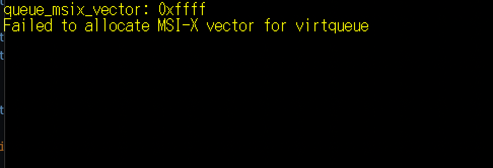
queue_msi_vectorがNO_VECTORになっていて設定できないな。
MSI-Xの設定ミスってんのかな。
ISRとMSI-Xについて
ISR
ISR(Interrupt Status Register)はVirtioデバイスの重要なコンポーネントの一つ。デバイスからホストへの割り込みの状態を通知する役割を持つ。具体的には、Virtioデバイスが生成する割り込みをホストが識別するために使われる。ここでの「設定」というのは主にデバイスドライバがISRをどのように読み取り、処理するかという点に関連する。
割り込みの通知
ISRは割り込みが発生したことをホストに知らせるためのフラグまたはビットフィールドを提供する。Virtioデバイスでは通常、特定の操作が完了したことを示すために割り込みを発生させる(例: I/O操作の完了)。
割り込みのタイプの識別
ISRには複数のビットが含まれている場合があり、それぞれが異なるタイプのイベントを示す。例えば、一つのビットがデータの受信を示し、別のビットがエラーを示すことがある。
MSI-X
上でたくさんMSI-Xのことを書いているので詳しくは書かないが、PCI規格で定められた割り込み方式の一つ。メモリバスへの書き込み動作によって割り込みの発生を伝える。
MSI-XとISRの違い
割り込みの指定
ISR
従来のISRは、複数のデバイスやイベントが同じ割り込み線を共有する可能性がある。このため、割り込みが発生すると、ドライバはISRをポーリングして、どのデバイスまたはイベントが割り込みを要求したのかを特定する必要がある。
MSI-X
各割り込みには独自のベクタが割り当てられ、直接特定のCPUコアにメッセージが送信される。これにより、ISRを確認する必要がなくなり、割り込み処理が大幅に効率化される。
割り込みの管理
ISR
割り込みが発生すると、ドライバはISRレジスタを読み出し、割り込みの原因を識別し、適切なハンドラを呼び出す。
MSI-X
割り込みの原因を識別するためにレジスタを読み出す必要がなく、割り込みの各インスタンスは独自のベクタを通じて直接処理される。
MSI-Xが有効な場合のISRの必要性
MSI-Xが有効な場合、通常、ISRは必要ない。MSI-Xは各割り込みソースに対してユニークな割り込みベクタを提供し、割り込みが発生すると直接適切なハンドラが呼び出されるため、割り込みの原因を識別するためにISRを確認する必要がなくなる。
MSI-Xが有効な場合、MSI-Xを使う方がベター。
だけど、非サポートのデバイスではISRを使うしかないらしい。
自分が使っているvirtio-blk-pciはMSI-Xが有効のはずだからやはりどこかの設定をミスっているのか...?
あれから色々試した結果、0か1をqueue_msix_vectorに登録する場合のみ、NO_VECTOR(0xffff)にならないことがわかった。
Vector番号を登録するんじゃなくてVector番号を登録したMSI-X Tableのインデックスを登録するということなのか。
→ そうっぽい。とりあえずVirtioデバイスとVirtqueueの初期化ができたので、
次はVIRTIO_PCI_CAP_NOTIFY_CFGの設定を行う。
VIRTIO_PCI_CAP_NOTIFY_CFG
デバイスがホストに特定のイベントが発生したことをどのように通知するかを定義する。
-
Virtqueueの操作
ドライバがVirtqueueにデータを配置し、デバイスに処理を依頼。デバイスはこのデータを処理し操作を完了する。 - 通知レジスタの書き込み
- ドライバのアクション: ドライバは、特定のVirtqueueの操作が完了した際に、Virtioデバイスの特定の通知レジスタ(VIRTIO_PCI_CAP_NOTIFY_CFGで指定された位置)に書き込みを行う。この書き込みは通常、Virtqueueのインデックスを含むことがある。
- デバイスの応答: この書き込みをトリガーとして、デバイスは関連するMSI-Xベクタを用いて割り込みを発生させる。
-
MSI-X割り込みの発生
デバイスがMSI-X割り込みを発生させると、設定されたMSI-Xベクタに基づいて割り込みは特定のCPUコアに直接送信される。 -
OSの割り込みハンドラの呼び出し
割り込みがCPUに到達するとOSの割り込みハンドラが呼び出され、適切な処理が行われる。このハンドラは、何らかの形でVirtqueueをチェックし完了した操作に対応する処理を実行する。
要するにドライバがVirtqueueにデータを配置して、ドライバがVIRTIO_PCI_CAP_NOTIFY_CFGに書き込みを行うことで、デバイスはVirtqueueに入っているデータの処理を開始する。その処理が終わればMSI-Xを用いた割り込みを発生させる。
Virtqueueの構造
ディスクリプタエリア
struct virtq_desc {
	uint64_t addr;	/* Address of buffer */
	uint32_t len;	/* Length of buffer */
	uint16_t flags; /* The flags as indicated above */
	uint16_t next;	/* Next field if flags & NEXT */
};
デバイスが処理するべきデータの情報を含むディスクリプタのリスト。
ドライバエリア
struct virtq_driver {
	uint16_t flags;
	uint16_t index;
	uint16_t ring[];
};
ドライバがデバイスに処理を依頼するディスクリプタのインデックスを保持する。ringがリングバッファであり、これがディスクリプタのindexのリストとなる。デバイスのVirtqueueにつき1つのvirtq_driverを持つ。
デバイスエリア
struct virtq_device_elem {
	uint32_t id;
	uint32_t len;
};

struct virtq_device {
	uint16_t flags;
	uint16_t index;
	struct virtq_device_elem ring[];
};
デバイスがデータの処理を完了した後、どのディスクリプタが使用されたかをドライバに通知するために使う。デバイスのVirtqueueにつき1つのvirtq_deviceを持つ。
for (int i = 0; i < num_desc; ++i) {
    queue->desc[i].addr = 0;
    queue->desc[i].len = 0;
    queue->desc[i].flags = 0;
    queue->desc[i].next = (i + 1) % num_desc;
}
ディスクリプタエリアの初期化を書いた。addrやlenは実際にバッファをデバイスに供給するときに設定する。
また、indexでつなぐリストを作るために(i + 1) % num_descとした。(末尾の場合には0が設定されるようにした)
デバイスにバッファを供給する手順
-
ディスクリプタの更新
ドライバはディスクリプタリングの空いているディスクリプタにバッファを配置する。データが大きくて一つのバッファでは収まりきらない時は、flagにVIRTQ_DESC_F_NEXTを設定してチェーン化する。 -
ドライバリングの更新
ドライバは、先ほど設定したディスクリプタの先頭インデックスをドライバリングの次のエントリに設定する。 -
メモリバリアの実行
デバイスが更新されたディスクリプタテーブルとデバイスリングを認識できるように適切なメモリバリアの設定を行う。x64なら下記の命令でおk。
asm volatile("mfence" ::: "memory");
-
インデックスの増加
ドライバリングに追加されたディスクリプタチェーンの数だけindexフィールドを加算する。 -
メモリバリア再実行
通知前に確実にindex更新を反映するためにメモリバリアを再実行。 -
デバイスに通知する
VIRTIO_PCI_CAP_NOTIFY_CFGが指定する通知レジスタに書き込みを行う。
上記の処理は書けた。deviceリングからのポップを実装する前に、virtio-blk側のモック実装書いて割り込みがちゃんと発生するかの動作確認をしたい。
一旦はカーネル側に実装するが、後でユーザーランド側に移行する。
virtio-blkに関する仕様書
virtio_blkのリクエスト構造体
constexpr int SECTOR_SIZE = 512;

struct virtio_blk_req {
	uint32_t type;
	uint32_t reserved;
	uint64_t sector;
	uint8_t data[SECTOR_SIZE];
	uint8_t status;
} __attribute__((packed));
図がすごいわかりやすい
virtq_descのaddrフィールドには、virtio_blk_req構造体の物理アドレスを設定する。
queueに書き込み→デバイスに通知 を行ったが、処理の完了を知らせる割りこみが発生しない。
考えられる原因
- virtio_pci_notify_cap から取得している通知用のアドレスの計算方法が間違っている。
- ディスクリプタに書き込んだデータが不正。
- MSI-Xの割り込み設定がちゃんとできていない。
割り込みがどうしても起きなくて手づまりしてるなあ
今書いている処理の流れ
- PCIバスからVirtioのデバイスを検出。
- 割り込み(MSI-X)の設定を行う。
- PCI CapabilitiesからVirtio Deviceの設定を行うためのCapabilityを取得する。
割り込みがついに発生した...!

原因はシンプルに該当のqueueをenableに設定していなかった。(めちゃくちゃしょうもない...)
virtio_blkに書き込み処理を送った結果、書き込み失敗のステータスが返ってくる。
二回目以降の割り込みが発生しない
書き込み失敗ステータスが返ってくる問題は、書き込みデータの長さをセクタサイズと合わせていなかったから起こった可能性が高い。あとは割りこみが発生しない問題を解決したい
二回目以降の割り込みが発生しない原因が判明した。
VIRTIO_F_EVENT_IDXをネゴシエートしていたから。これは、通知の仕組みが従来とは変わるので一回目が成功し、二回目以降の割り込み全く起きなかった。今のところ、この機能ビットは必要ないのでネゴシエートしないようにする。
ようやくvirtio_blkのドライバ実装できた。ちまちまやってたら三か月ぐらいかかってしまった~
次はvirtio_netに対応させよう。