iTranslated by AI
Building a Brainfuck Instruction Set CPU with Friends


This is an article for the 13th day of the Kisarazu KOSEN Advent Calendar.
Introduction
Most people have probably at least heard the name Brainfuck. Unlike common programming languages, Brainfuck is known as one of the esoteric programming languages, written using only eight symbolic characters. With only that information, some might think Brainfuck is just an obfuscated programming language. However, that is not the case.
Brainfuck is a programming language composed of only the following eight instructions. Despite its simplicity, it is Turing complete.
| Instruction | Description |
|---|---|
| > | Increment the data pointer. |
| < | Decrement the data pointer. |
| + | Increment the byte at the data pointer. |
| - | Decrement the byte at the data pointer. |
| . | Output the byte at the data pointer. |
| , | Accept one byte of input, storing its value in the byte at the data pointer. |
| [ | If the byte at the data pointer is zero, jump forward to the command after the corresponding ]. |
| ] | If the byte at the data pointer is nonzero, jump back to the command after the corresponding [. |
My understanding of Brainfuck deepened during a chat with a classmate in a KOSEN class. He showed me a program he wrote to display "Hello World" in Brainfuck. I've forgotten his specific code, so I'll quote the code from Wikipedia.
++++++++[>++++[>++>+++>+++>+<<<<-]>+>+>->>+ [<]<<-]> >>.>---.+++++++..+++.>>.<-.<.+++.------.--------.>>+.>++.
When I saw this, I realized it was a very sophisticated programming language. It doesn't just increment
When I looked at the Brainfuck program, I noticed three things:
- You can understand everything happening under the hood during execution (in fact, you have to, or you can't program it).
- The instruction set is neither too small nor too large.
- Handling memory feels like low-level programming, but it has a different kind of excitement compared to Assembly.
The interesting part is the "low-level feel" mentioned in point 3. Brainfuck can be thought of as consisting of instructions with opcodes and operands, much like Assembly. However, unfortunately, Brainfuck is not Assembly. Most Brainfuck source code is executed via an interpreter.
That's when I thought: I want to run Brainfuck source code on hardware without going through an interpreter. I hit it off with two others I was talking to about Brainfuck, and we decided to build a "computer where you input Brainfuck code, and a CPU made of logic ICs performs the calculations."
As a side note:
I wondered if it would be difficult to execute Brainfuck directly on hardware like Assembly. What do Brainfuck interpreters and compilers actually do? These questions surfaced.
In conclusion, I found that finding the jump address for Brainfuck loop instructions is not trivial.
For example, when executing the [ instruction, if the value of the memory currently being pointed to is 0, you must jump to the corresponding ]. Brainfuck interpreters and compilers explicitly indicate where to jump by pre-calculating the jump destination.
While this means I don't have to build a high-performance ALU and there are no data types, it also means I have to find the jump destination via hardware.
What is the goal?
Realize hardware that accepts Brainfuck code and executes the program
This involves designing a custom CPU that executes the Brainfuck instruction set and implementing it with ICs. I want to build it.
I want to create something exciting, like the work of someone who built a custom CPU using relays.
Roadmap
Since it is difficult, I will divide it into
- Overall architecture and state transition diagrams for each instruction are written.
- Logic circuit diagrams are created.
- Circuit diagrams including components are created.
- Hardware architecture is created.
- Build it.
1. Overall architecture and state transition diagrams for each instruction are written.
I will consider the minimum functions and configuration to build a CPU.
I will think about how to connect each element (e.g., registers, ALU) to execute Brainfuck instructions.
Also, I will create a state transition diagram of how register values and memory values change for each instruction.
2. Logic circuit diagrams are created.
In this stage, I will create logic circuit diagrams using a logic circuit simulator.
At this point, I will verify how data flows and is calculated using buses. I won't discuss specific arithmetic units or bus configurations here.
I will test whether correct results are obtained by fetching instructions from ROM.
3. Circuit diagrams including components are created.
In this phase, circuit diagrams are created. Based on the logic circuit diagrams, we will discuss what elements to use for each module's configuration and the specific wiring setup.
I expect this to be a grueling task. For an 8-bit system, we need to wire 8-bit buses, making the circuit diagrams extremely large and complex, which will lead to a determined manual debugging process.
4. Hardware architecture is created.
We will discuss the physical configuration of the hardware that was omitted from the circuit diagrams.
5. Build it.
Procure parts and build it!!!!
Progress
A group of three of us, including myself, is working steadily. Since we all live in the dormitory, we gather at the whiteboard after the evening roll call to move forward.
The overall architecture diagram is complete. Note that we are using our own internal naming conventions.
There are four registers held:
- Address (to reference values)
- Flag (to flag whether to skip a loop)
- Registers to count loop nesting x 2 (
[and])
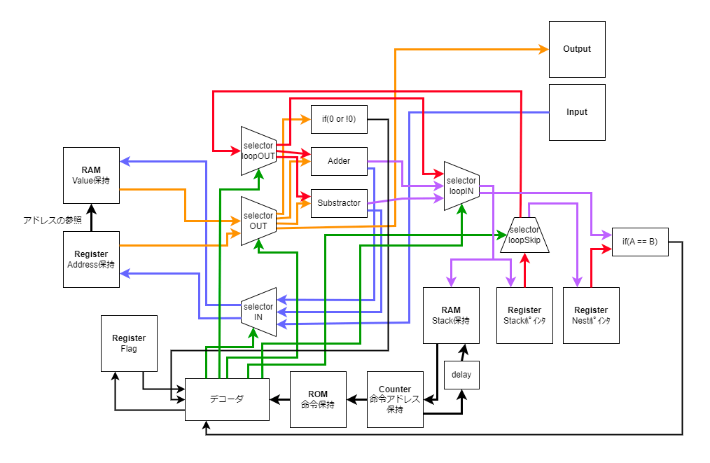
Overall Architecture Diagram
A diagram was created to show how data is passed or evaluated by each module for every clock cycle.
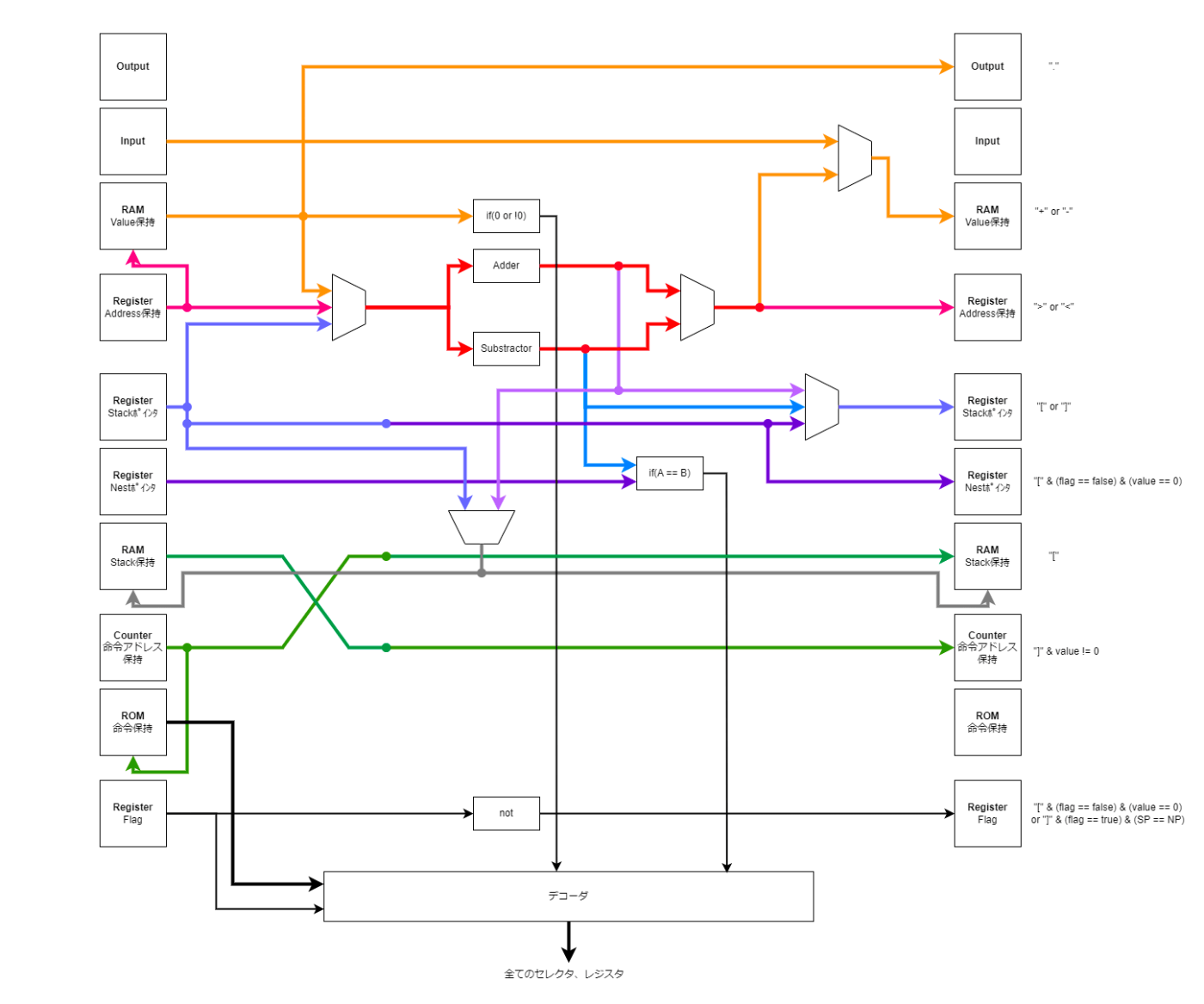
Sequence diagram when an instruction is executed
Once we reached this point, I wanted to implement it in a logic circuit simulator, but there was one problem. That is, the decoder had been treated as a black box until now. The selector that sorts data is connected to the decoder that interprets the instructions on the back end, but the consideration of the decoder's specifications remained.
Currently, we are assigning bit strings corresponding to instructions and designing the decoder.
This is a truth table created by one of our team members. It is laughably brute-force. We will use this truth table as a starting point to verify its validity as a group.
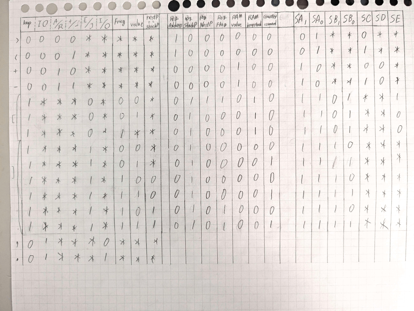
Summary
I wrote about the background and progress of trying to build a CPU with the Brainfuck instruction set.
The more I work on it, the more I realize how rational existing CPU instruction sets are.
I can't wait for the Brainfuck computer to be completed.
Discussion